Removal & replacement information – Profax AEC 200 User Manual
Page 22
21
20
REMOVAL & REPLACEMENT INFORMATION
A.) DRIVE ROLL (Fig. 1)
1.) Unlatch swing out arm and rotate out away from drive roll.
2.) Remove palnut from end of motor shaft.
3.) Lift drive roll off shaft.
4.) Install new drive roll making sure key way lines up with
woodruff key.
5.) Replace palnut.
6.) Readjust tension on swing out arm.
B.) DRIVEN ROLL (Fig. 1)
1.) Unlatch swing out arm and rotate out away from drive roll.
2.) Remove one of the retaining rings on the driven roll
bearing pin.
3.) Remove pin and driven roll.
4.) Install the replacement driven roll, inserting pin and replace
retaining ring.
5.) Return and readjust tension on swing out arm.
C.) MOTOR
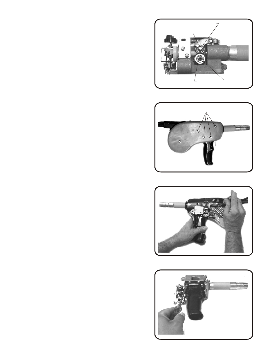
1.) Remove front cover.
2.) Remove the four screws on rear cover to release housing.
(Fig. 2)
3.) Remove motor leads on terminal strip. (16 black and 23 red)
(Fig. 3)
4.) Remove the three screws holding gun handle to housing.
(Fig. 4)
5.) Remove handle assembly from housing. (Fig. 5)
Remove the motor insulator and O-ring, set
them aside for use when reassembling.
6.) Remove motor from gun handle. (Fig. 5)
7.) Remove drive roll and place on replacement
motor making sure key way lines up with
woodruff key, replace palnut.
8.) Install new motor in handle, making sure
motor lead wires are in the groove provided in
the handle. Replace motor insulator and
O-ring in proper place.
9.) Reassemble gun making sure motor leads are
out of way of the movable arm on the rheostat.
D.) JOG BUTTON SWITCH
1.) Remove retaining nut on jog button switch.
2.) Unsolder Electrical leads.
3.) Solder electrical leads to new job button switch.
4.) Replace in button of handle and replace retaining nut.
E.) GAS VALVE (Fig. 6)
1.) Remove front and rear covers.
2.) Remove retaining ring from trigger pin, remove palnut
from valve pin, remove the pin, trigger, trigger spring and
the valve guide.
3.) Remove retaining nut on diaphragm assembly, remove
pin and diaghram.
*IMPORTANT: Before gun assembly adjust gas valve
as follows:
A.) Attach shielding gas supply hose from AEC 200 gun
to the flowmeter regulator on gas supply source.
B.) Full gas flow must be attained before microswitch
is actuated. Pull the trigger and adjust the palnut
to achieve proper gas flow. An allen screw in the
trigger casting allows for proper gas flow
adjustments before microswitch is actuated.
C.) With the gun trigger fully depressed adjust the
microswitch actuating screw, in the trigger
casting, until the microswitch makes first click.
While still holding the gun trigger fully
depressed, check for at least 0.30" of movement in
the microswitch actuating button.
D.) Reassemble the Gun.
4.) Install new valve components.
F.) MICROSWITCH
1.) Remove the microswitch insulator and microswitch.
2.) Remove electrical lead wires.
3.) Connect electrical lead wires to new microswitch.
4.) Replace microswitch and insulator to housing.
G.) WIRE FEED SPEED RHEOSTAT
1.) Remove front cover.
2.) Disconnect electrical lead wires from terminal
strip inside rear cover. (Lead's #13, 14 & 15)
3.) Remove rheostat screws from housing and
remove rheostat.
4.) Replace new rheostat with screws previously removed.
5.) Reconnect the marked lead wires to corresponding
terminals on terminal strip in rear cover.
WIRE GUIDE HOUSING
PALNUT
VALVE GUIDE
VALVE PIN
VALVE SPRING
RETAINING NUT
TRIGGER
TRIGGER SPRING
TRIGGER PIN
ACTUATING
SETSCREW
RETAINING RING
DIAPHRAM
RETAINING RING (2)
DRIVE ROLL
Figure 1. Drive roll replacement
FOUR SCREWS
PAL NUT
Figure 2. Removing rear cover
Figure 5. Gun handle and motor withdrawl.
Figure 6. Adjusting gas valve
Figure 3. Removing motor leads
from terminal strip
Figure 4. Removing the three screws holding
gun handle to housing.
PIN