Aec 200-1, Control boxes, Model aec 200-1 – Profax AEC 200 User Manual
Page 9: Warning, Caution
7
6
CONTROL BOXES
For use in connecting the AEC 200 Welding Gun to a constant voltage welding power source.
WARNING
Disconnect all electrical power before installation
of this control unit. Touching live electrical
parts can cause fatal shock.
CAUTION
Shut off engine before attempting any installation.
Moving parts and live electrical connections
can maim.
AEC 200-1
TO INSTALL:
1.) Remove top cover from control unit.
2.) Install the multi-conductor cord from the AEC 200 Welding Gun through the access hole in the front panel of
the control box and connect the numbered wires to the corresponding numbers on the 8 pole terminal
strip TS1.
3.) Connect the contactor control cord on the back of the control box to the contactor control
receptacle on the welding power source. (See note below).
4.) Connect the 115 volt A.C. power cord from the control box to a 115 volt A.C. power source.
5.) Replace top cover and tighten screws.
NOTE
Terminals 1 and 2 on the four pole terminal strip TS2 are for use with welding power sources requiring a normally open set of
contacts for power source contactor operation. This set of contacts will close when the gun switch is operated.
Terminals 3 and 4 on the four pole terminal strip are for use with welding power sources requiring 115 VAC to be supplied to the
power source for contactor operation.
This control box comes with the contactor control cord connected to terminals 1 and 2.
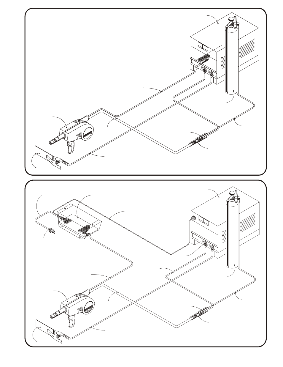
CONSTANT VOLTAGE POWER SOURCE WITH 24 VOLT STRIP
CONSTANT VOLTAGE POWER SOURCE WITH AEC 200-1
MODEL AEC 200-1
115 VOLT AC
POWER CABLE
MODEL
AEC 200-1
CONTROL
115 VOLT AC
*PLUG NOT INCLUDED
MULTI CONDUCTOR
CABLE TO TERMINAL
STRIP IN CONTROL BOX
MODEL
AEC 200
SPOOL GUN
WORK
WORK
MODEL
AEC 200
SPOOL GUN
CABLE TO 24 VOLT
TERMINAL STRIP IN
POWER SUPPLY
POSITIVE
NEGATIVE
CABLE
BOOT
HOSE TO GAS
SUPPLY
GAS CYL.
POWER
SOURCE
CONNECTION
BLOCK
WELDING CABLE
TO WORK
GAS & WELDING
CABLE
WELDING CABLE FROM
NEGATIVE OUTPUT TERMINAL
ON POWER SOURCE
GAS & WELDING
CABLE
GAS
CYLINDER
HOSE TO GAS
SUPPLY
CONNECTION
BLOCK
CABLE
BOOT
WELDING CABLE TO
“GUN” STUD ASSEMBLY
ON CONTROL BOX
POWER
SOURCE
CONTACTOR CONTROL
CABLE TO CONTACTOR
CONTROL RECEPTACLE
ON POWER SOURCE
(see installation instructions)
POSITIVE
OUTPUT
TERMINAL