Using an optional conveyor with the l-350, Installing the optional tr-10 reel assembly, Figure 11 – Rena L-350 User Manual
Page 14
-12-
USING AN OPTIONAL CONVEYOR WITH THE L-350
Warning: Before connecting a conveyor to the power outlet on the L-350, please be sure
it meets the following electrical specifications: 115 VAC and a maximum current draw of 1
amp or less.
1. Slide out and remove the receiving tray. Position the conveyor against the labeler.
2. Plug the power cord from the conveyor into the conveyor receptacle on the rear of the
L-350. Turn on the conveyor’s power switch. The conveyor will now be
stopped/started by the tabber/labeler.
3. Depress the FEED switch on the labeler. The conveyor will start working. Depress
the FEED switch again and the conveyor will stop.
INSTALLING THE OPTIONAL TR-10 REEL ASSEMBLY
The reel assembly will allow the machine to utilize tabs supplied on a roll instead of the
standard fan-folded tabs. This assembly will also allow the L-350 to utilize stamps
supplied on a roll. The major benefits of this are fewer threading cycles as a roll can hold
as many as 10,000 tabs.
1. Remove the standard label feed tray.
2. Mount the reel assembly to the machine by hooking the rear bracket to the center tie
bar of the head assembly.
3. Pivot the reel assembly forward to seat
the front bracket over the front tie bar of
the head assembly.
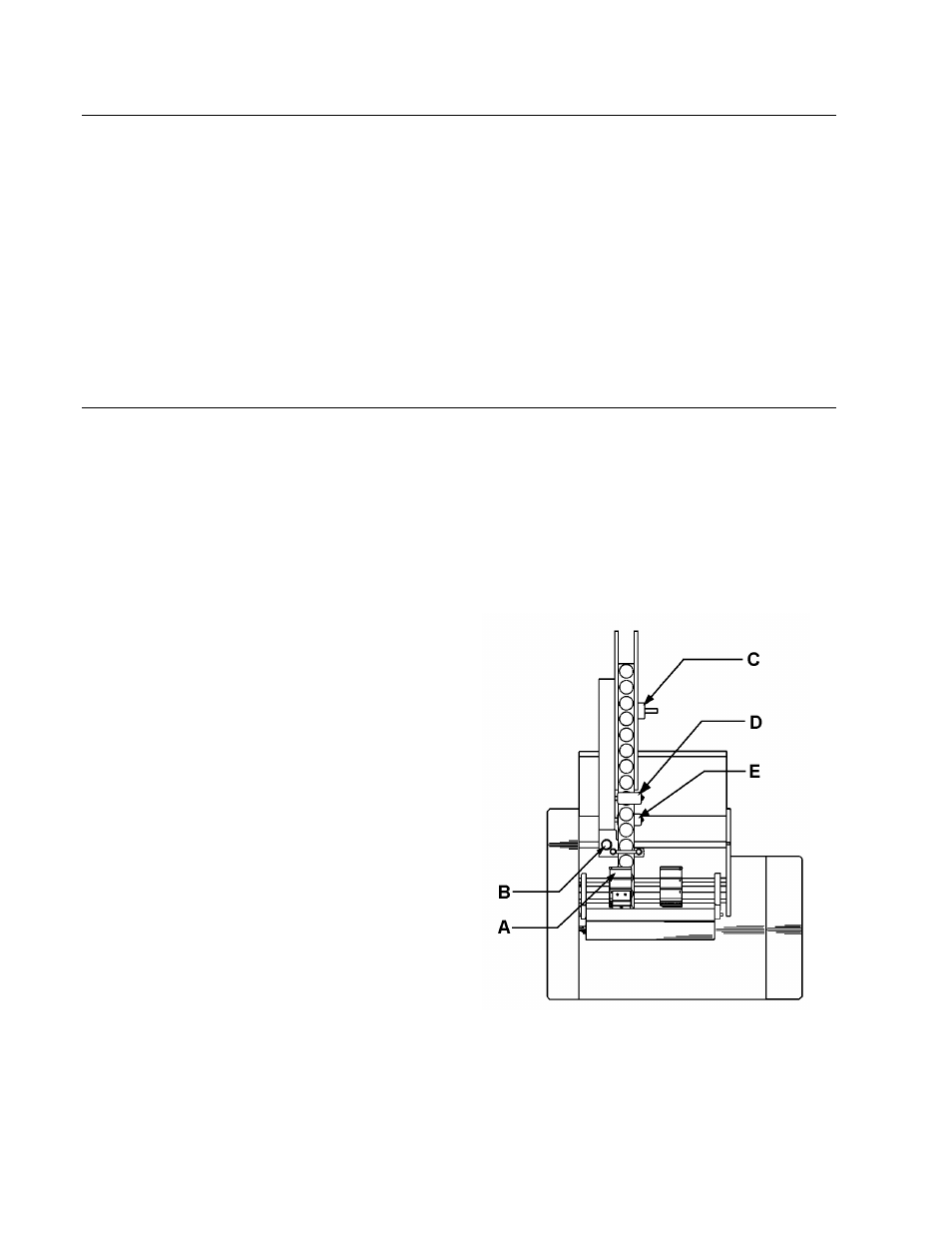
4. To position the reel, slide the whole
assembly on the tie bars until the
tracking guides [Figure 11A] are over
the desired tabbing area.
5. Lock the reel in place with the
thumbscrew [Figure 11B].
6. Remove the reel support guide [Figure
11C] by pulling it off the reel shaft.
7. Mount a spool of tabs so it unwinds in a
COUNTER-CLOCKWISE direction with
tabs facing up. Reinstall the support
guide removed in step 6.
8. Route the tab supply around the brake
roller [Figure 11D] to the guide roller
[Figure 11A] in such a manner that the
tabs contact the brake roller while the
backing paper contacts the guide roller.
9. Loosen the two tracking guide screws and separate the guides.
10. Route the tab supply between the guides and clamp support rails.
Figure 11