Royal Cozyfires Super Hotbox Toaster MK4 - LPG User Manual
Page 16
16
HM83 010710
Section 3 – Maintenance & Servicing
3.1
REMOVAL OF DEBRIS OR SOOT
Super Hot Toaster Mk4
Allow the appliance to cool for two to three hours before removing all of the fibre components for cleaning purposes. Once all the fibre is
removed, check that no debris is located in the burner holes of the appliance. If any debris is located, carefully remove any foreign matter
from the burner holes.
Any soot deposits or debris left on the fibre components may be removed by using a soft brush. Brush with the component held away from
your face so that you avoid inhaling the dust. CROSSLEE plc DOES NOT recommend the use of a normal vacuum cleaner, which may
blow dust back into the room.
To ensure that the release of fibres from these RCF articles is kept to a minimum, during installation and servicing, CROSSLEE
recommend that a HEPA filtered vacuum is used to remove any dust and soot accumulated in and around the appliance before and after
working. When replacing these articles, CROSSLEE recommend that they are NOT broken up, but are sealed in heavy duty polythene
bags and clearly labelled as RCF WASTE. This is not classified as hazardous waste and may be disposed of at a tipping site licensed for
the disposal of industrial waste. Protective clothing is not required when handling these articles although CROSSLEE recommend you
follow the normal hygiene rules of not smoking, eating or drinking in the work area and to always wash your hands before doing so.
3.2
SERVICING COMPONENTS BELOW THE BURNER
To gain access to the components below the burner, remove the fibre components and the burner unit from the firebox.
CLEANING OR REPLACING THE INJECTOR (Fig. 28).
Unscrew the compression nuts from the gas control to the injector.
Remove the formed pipe.
Unscrew the injector from the burner.
Replace
in
reverse
order.
REPLACING THE GAS CONTROL (Fig. 29).
Disconnect the two formed pipes from the gas control.
Disconnect the thermocouple from the gas control.
Remove the control knob.
Undo the retaining nut on the facia panel.
Replace
in
reverse
order.
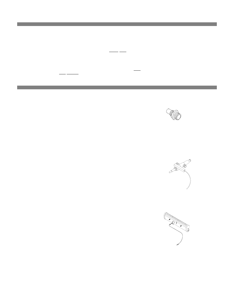
REPLACING THE MAIN BURNER & THERMOCOUPLE (Fig.30).
(Atmospheric sensing device)
Unscrew the two fastening nuts and washers from the rear of the burner unit.
Remove the stainless steel baffle and spacer plate.
Disconnect the formed pipe connecting the gas control and injector.
Unscrew the injector from the main burner
Unscrew the two fastening nuts and washers from the front of the burner unit.
Remove the main burner.
Unscrew the locknut, retaining the thermocouple.
Remove the thermocouple.
Replace
in
reverse
order.
Fig. 28
Fig. 29
Fig. 30