SP Controls PX2-NRC-1142 User Manual
Page 12
RS-232 Command Format
RS-232 command data can be represented in three different formats: ASCII, hexadecimal, and deci-
mal. A single command is usually represented in just one format, but it could given in two, or even all
three. To represent these inside the command, different “tags” will be used.
ASCII:
Characters enclosed inside single quotes will be read by the NRC as ASCII.
Example:
This would be sent as an ASCII string ‘PWR<space>1’ (quotation marks will not be sent).
Hexadecimal:
A pair of characters preceded by a dollar sign will be interpreted as a
hexadecimal byte (Note: the only valid hexadecimal characters are 0-9
and A-F, and they must be sent in pairs).
Example:
This would be sent as the hexadecimal string shown above. The dollar sign indicates that the next
characters will be hexadecimal and is not actually sent. The commas are separators between bytes.
Decimal:
Untagged characters will be sent as decimals.
Example:
This command would be interpreted as four bytes with the decimal values 86, 00, 13, and 10.
Delays:
Delays between bytes are tagged with a lowercase ‘d’ followed by the time in
seconds (s) or milliseconds (m)
Example:
This would send the same command as in the ASCII example above, followed by a delay of three
seconds, and then send the same ASCII command a second time.
Mixed commands: Commas separate the different formats and different hex or dec bytes.
Example:
This command would be sent as ASCII bytes ‘POFF’, followed by hexadecimal byte ‘0A’, then hexa-
decimal ‘0D’, then a 500 millisecond delay, then ASCII ‘POFF’I, ‘0A’, and ‘0D’ in hexadecimal again.
Carriage Returns and Line Feeds: Many devices require that a carriage return and possibly a line
feed follow every command. A carriage return may be represented by decimal 13 or hex $0D. A line
feed may be represented by decimal 10 or hex $0A.
Testing RS-232 Commands
Once you’ve created the command, if the RS-232 device is connected, you can click the Send Test
To button. This will send the command you just created to the RS-232 port specified in the adjacent
pull-down menu. If the device responds to commands, you will see the response in the Device Reply
pane (you’ll need to specify if you wish to view the reply as ASCII or hex by clicking the appropriate
radio button).
Creating an IR Driver
To start, click on the ‘...’ icon next to the IR port you wish to configure with a driver. You’ll see a list of
IR drivers. If a driver for your device exists on that list, select it. Otherwise, you’ll have to click Create
New Driver. Just like with the RS-232 driver, fill in the Driver File Name fields completely (no spaces
or special characters are allowed in any field, except for hyphens and underscores).
To learn the IR codes, you’ll need to have a PixiePro Modular Panel connected to the SP Bus (see
Wiring the NRC). For now, simply connect the RJ-45 port on the Modular Panel to one of the SP Bus
ports on the NRC with CAT5 cable. To announce the MP on the Bus, press any button on the MP and
while holding it down, insert a paperclip into the hole marked insert paperclip to learn (see page 32 for
more information).
You should immediately see the question mark icon next to the PX2-MP-IR node turn into a happy
face icon. Your Modular Panel is now on the SP Bus and ready to help your NRC learn IR codes.
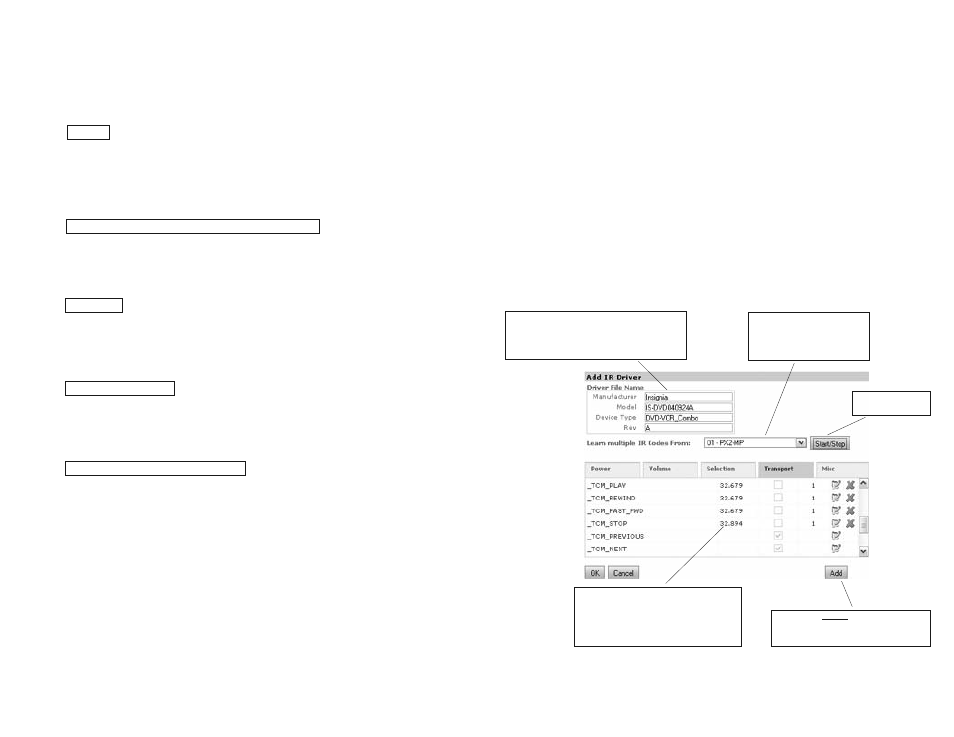
Learning IR Codes
Click the Start/Stop button in the Add IR Driver window to initiate IR learning on the Modular Panel.
The Panel will chirp and you should see all the LEDs flash quickly and then darken. This means that
you’re ready to start learning codes.
.
All four “Driver File Name” fields are re-
quired (remember, no spaces or special
characters are permitted, but under-
scores and hyphens are allowed)
Use this pull-down menu to
select which Modular Panel
you’ll be learning from, if
you have more than one
Click here to start
and stop learning
You should never need to add an IR
code manually; this function is only
for SP Controls’ engineers only
Watch the carrier frequency to make
sure that the remote gives approxi-
mately the same result for all codes. If
these values vary greatly, that could
mean learning difficulties
21
‘PWR 1’
$BE,$EF,$03,$06,$00,$BA,$D2,$01,$00,$00,$60,$01,$00
86,00,13,10
'POFF',$0A,$0D,d500m,’POFF’,$0A,$0D
‘PWR 1’,d3s,’PWR 1’
20