Post-installation calibration, Model 742, Reference tone direct output – Studio Technologies 742 2005 User Manual
Page 15
Model 742 User Guide
Issue 2, May 2005
Studio Technologies, Inc.
Page 15
Model 742
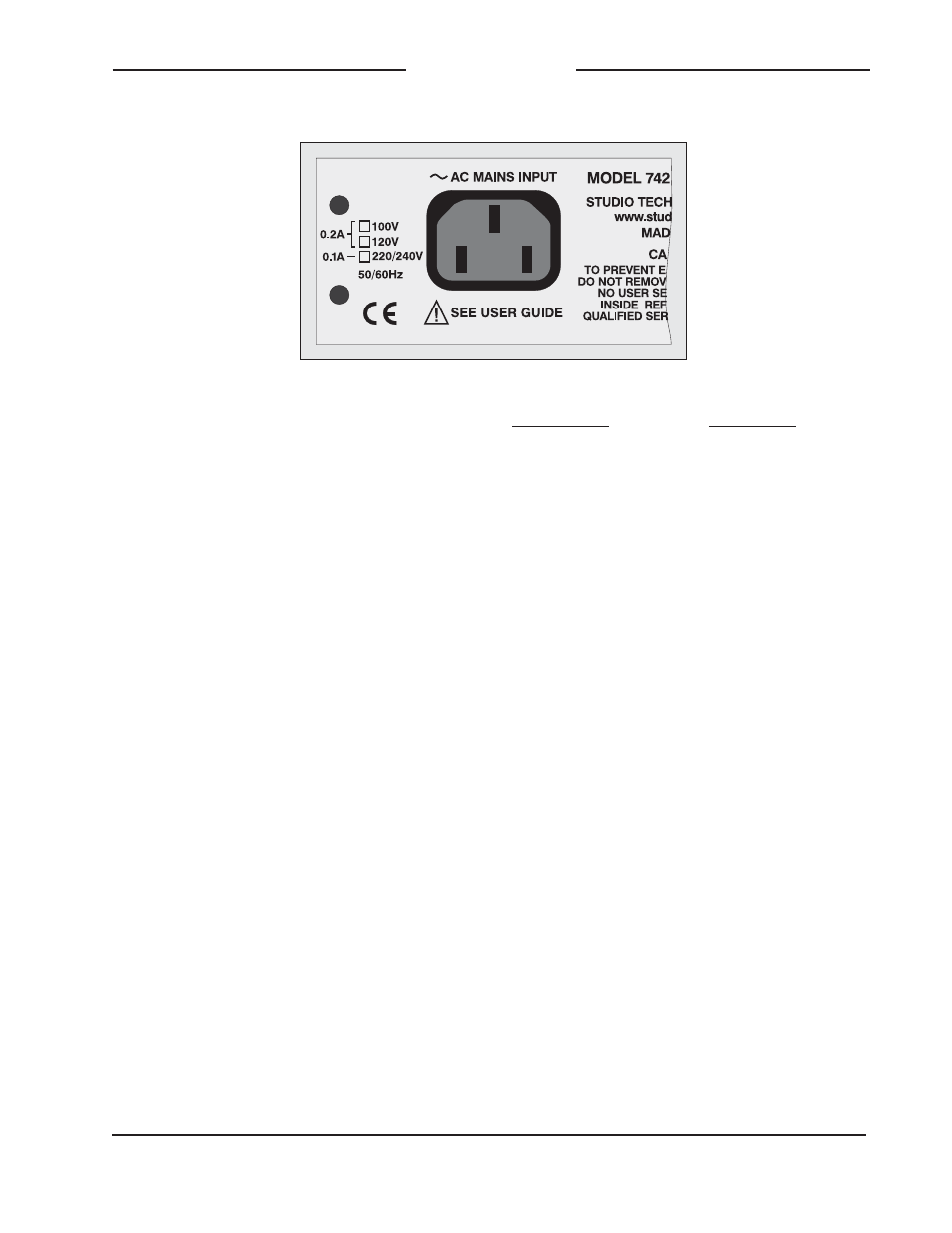
120 volt operation and are supplied with
an internal 0.2 A, 5 x 20 mm time-lag fuse.
Units shipped to Japan are factory con-
figured for 100 volt operation and use the
same 0.2 A, 5 x 20 mm time-lag fuse. Units
configured for 220/240 volt operation are
supplied with a 0.1 A, 5 x 20 mm time-lag
fuse.
Before connecting the Model 742 to AC
mains power, determine the actual mains
voltage and confirm that the Model 742
has been configured appropriately. As
should be expected, an incompatible
mains voltage configuration could seri-
ously damage the unit. Should it be nec-
essary to change the unit’s mains voltage
configuration contact Studio Technologies’
technical support personnel for details.
The Model 742 uses a 3-pin IEC 320
C14-compatible inlet connector to mate
with a detachable mains cord set. For
units shipped to North America and
Japan, a cord is supplied that has a North-
American (NEMA 15L) standard plug on
one end and an IEC 320 C13-compatible
connector on the other. Units bound
for other destinations require that the
appropriate cord set be obtained. The wire
colors in the mains cord must conform to
the internationally recognized color code
and should be terminated accordingly:
Connection Wire
Color
Neutral (N)
Light Blue
Line (L)
Brown
Earth/Ground (E)
Green/Yellow
Because the Model 742 contains no AC
mains on/off switch it will begin operation
as soon as AC mains power is connected.
To confirm that the Model 742 is operating
the LED indicator labeled PWR/TONE will
light. This LED is located below the tone
function’s on/off switch.
Post-Installation
Calibration
Reference Tone Direct Output
If the reference tone direct output is used,
it is important to confirm that its output
level is correct for the installation. In most
cases, the output level will need to be
adjusted to match the precise require-
ment of the system. This is because the
load applied to the output may very well
be different from the 100 k ohm load that
is applied during testing at the factory. As
previously noted, while the output circuitry
is capable of driving loads of 600 ohms or
greater, the output level will drop slightly
as the load impedance changes, espe-
cially as it approaches 600 ohms.
Detail of back panel showing AC mains power connector