Model 742, Labeling the unit for clarity – Studio Technologies 742 2005 User Manual
Page 16
Issue 2, May 2005
Model 742 User Guide
Page 16
Studio Technologies, Inc.
Model 742
Depending on the Model 742’s internal
configuration the tone frequency will be
either 400 Hz or 1 kHz. A trim potentiom-
eter allows adjustment of the output level
over a range of approximately +3 to +7
dBu. The trim pot is accessible by way of
a small access hole in the back panel, ad-
jacent to the reference tone direct output’s
¼-inch jack. At the factory this output is
loaded with 100 k ohms and then the trim
pot is adjusted to give an output level of
+4 dBu.
In practice, calibrating the output level is
quite simple:
1. Confirm that the reference tone direct
output is terminated with its installa-
tion-specific load impedance.
2. Ensure that the Model 742 is connect-
ed to AC mains power.
3. Using an appropriate adapter cable,
connect a high-input-impedance audio
level meter directly across the refer-
ence tone direct output. Ensure that
this meter connection does not remove
the normal load! The level meter must
be a precision device that’s intended
for audio use—a general-purpose volt-
meter is not adequate!
4. While carefully observing the level
meter, adjust the trim pot to give the
desired output level.
Labeling the Unit for Clarity
Once the Model 742 has been installed,
installation-specific labeling of the front
panel may want to be performed. This ad-
ditional clarity can greatly assist operators
in correctly using the unit. For example,
instead of the first line input channel having
the factory-standard text INPUT 5, it could
reflect its exact function, such as TAPE 1.
The unit’s front-panel graphics were specifi-
cally created to simplify the task of adding
custom labels. Each front-panel section
heading text is underlined with a horizontal
green line, which, besides looking pretty
sharp, is intended to serve as a “guide”
for adding installation-specific labels. The
distance from the guide line to the top of
the front panel was specifically designed
to allow ¼-inch-high label material to fit
correctly.
Detail of back panel showing reference tone
direct output connector and associated level
trim pot
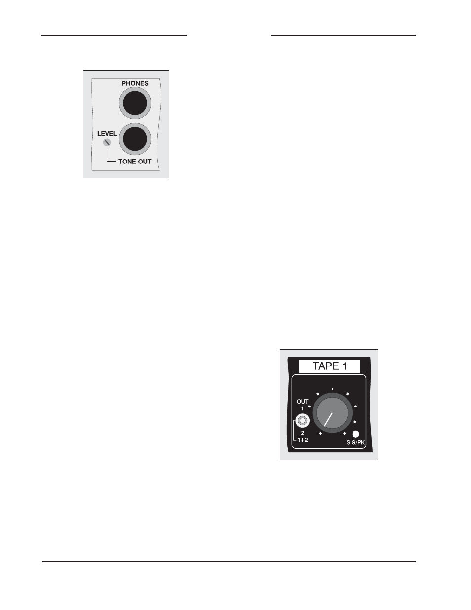
Detail of front panel showing installation-specific
label