Model 750, Configuration dip switches – Studio Technologies 750 User Manual
Page 21
Model 750 User Guide
Issue 3, May 1997
Studio Technologies, Inc.
Page 21
Model 750
tion DIP switches. One is shipped with
each Model 750, being attached to the
front panel by means of two screws.
Where the Model 750 is physically located,
and who will be operating the unit, will
dictate whether the security cover remains
in place or is permanently removed. In a
facility where many operators have access
to the unit, it may be best to set the con-
figuration DIP switches to match the needs
of most operators, then replace the cover.
In a facility where only a few operators
have access, such as an SNG vehicle, the
cover can stay off to allow quick access to
the features.
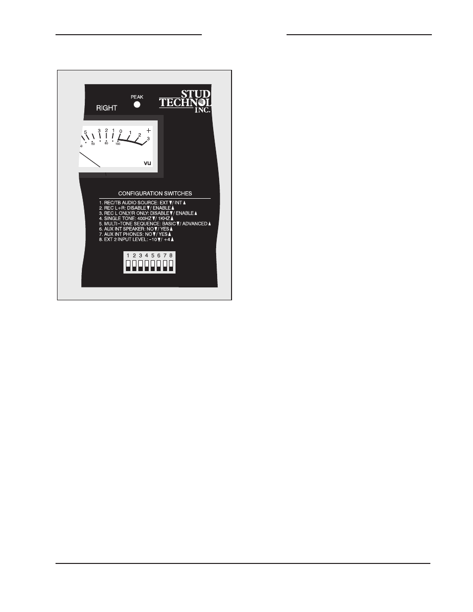
A brief description of the function of each
configuration DIP switch is contained on
the front panel, directly above the DIP
switches. A more detailed description is
provided here:
1. REC/TB AUDIO SOURCE: EXT ▼▼▼▼▼ / INT ▲▲▲▲▲
This switch selects which audio source will be
used by the voice record and talk back sections.
In the down position the external audio source is
selected. In the up position the internal micro-
phone will be used.
Be careful with this switch! In most cases an
external audio source will not be connected and
the internal microphone needs to be selected for
use. Its easy to accidentally set DIP switch 1 to
the down position and have no source of record
and talk back audio.
2. REC L+R: DISABLE ▼▼▼▼▼ / ENABLE ▲▲▲▲▲
This switch selects whether the setup sections
L+R voice segment can be recorded. In the down
position recording cannot take place. In the up
position recording can take place.
This feature can prove useful where a semi-
permanent L+R voice segment needs to be re-
corded. By placing the switch to the down
position, the L+R voice segment cannot be
changed.
Configuration DIP Switches
Studio Technologies is sorry to report that
the 8 configuration DIP switches had to be
placed on the front panel. We tried to
place them on the back panel where
theyd be hard to reach, or inside the unit
where youd never find them, but we just
couldnt find the spacejust kidding! The
8 configuration DIP switches are located
on the front panel where you can easily
get at them. These switches allow impor-
tant operating parameters to be easily
configured, and then quickly changed
on-the-fly as operating requirements
dictate. The factory default is to have all
8 switches set to the up position.
A clear plastic security cover can be
used to prevent access to the configura-
Figure 8. Detail of front panel showing
configuration DIP switches