Model 750 – Studio Technologies 750 User Manual
Page 25
Model 750 User Guide
Issue 3, May 1997
Studio Technologies, Inc.
Page 25
Model 750
an indication of the center of the pan pots
rotation. In this position signal is sent
essentially equally to both the left and
right buses.
The pan circuitry is a constant-energy
type, ensuring that as the signal is
panned across the left/right stereo field,
the total energy sent to the buses remains
constant. A 3dB level increase will be
observed on the left VU meter when the
pan pot is set to the fully counterclockwise
position. Youll observe a 3dB increase on
the right meter when fully clockwise.
Bus Assignment
Located below the level and pan controls
are two buttons, labeled AUX and MAIN.
These buttons control the connection of
the audio signal coming from the pan pot
to the AUX and main audio buses. In
addition to audio signals, the AUX button
also controls the status of the AUX inter-
rupt control bus.
AUX Bus Assignment
The assignment button labeled AUX con-
trols the routing of the left and right audio
signals to the AUX audio bus. In the off
(out) position, signals are not routed to the
bus, and the AUX interrupt control bus is
not enabled. In the on (in) position, the
signals are routed to the AUX audio bus,
and the AUX interrupt control bus is en-
abled. A status LED, orange in color and
visible through a window in the button,
lights whenever the button is in the on
position.
Note that enabling the AUX interrupt
control bus may, or may not, have a
noticeable effect on the Model 750s
operation. It will depend upon the settings
of configuration DIP switches 6 and 7.
Main Bus Assignment
The button labeled MAIN controls the
assignment of the left and right audio
signals to the main audio bus. In the off
(out) position, the signals are not con-
nected to the main bus; in the on (in)
position, the signals are connected to the
main audio bus. A status LED, green in
color and visible through a window in
the button, lights whenever the button is in
the on position.
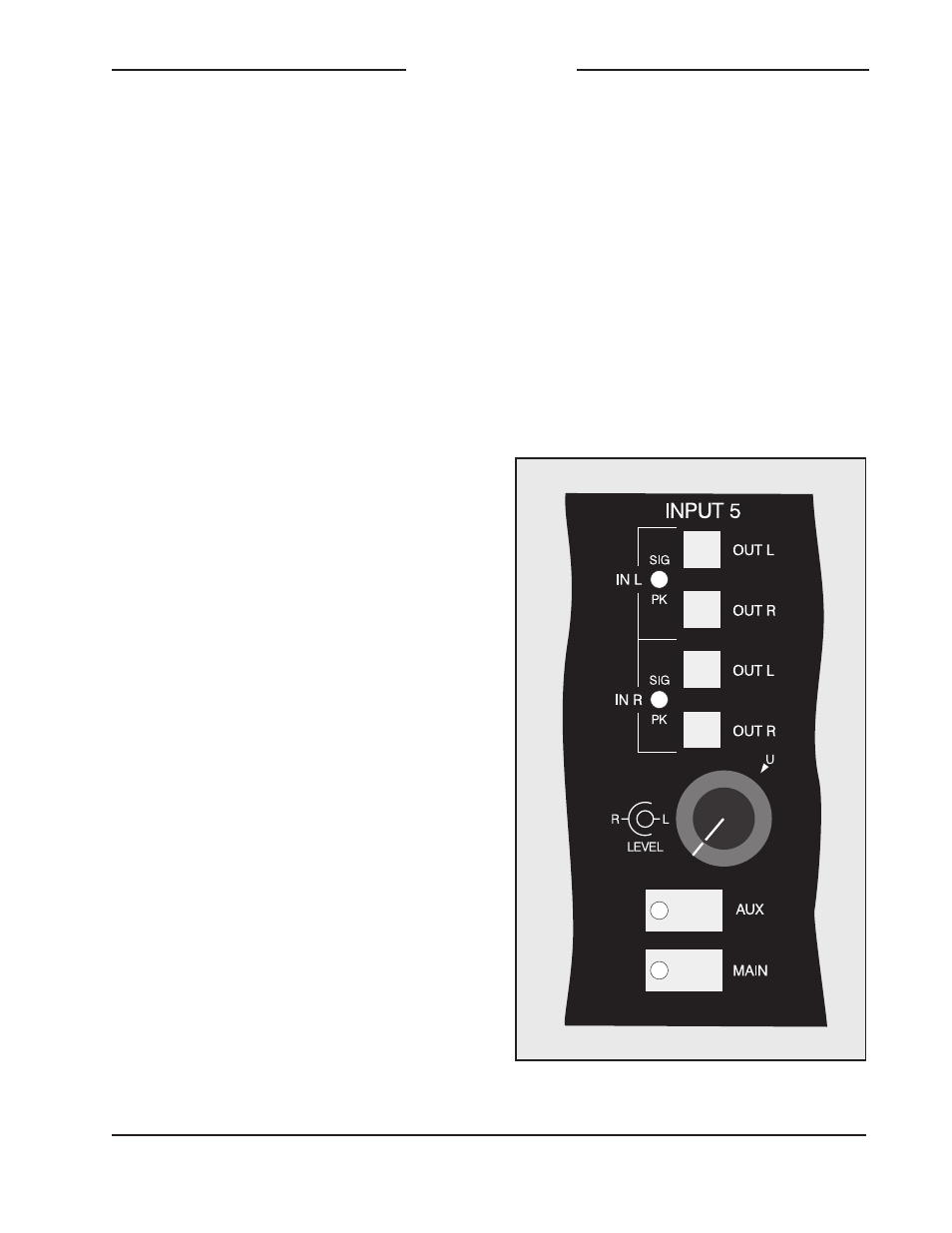
Figure 10. Detail of front panel showing stereo
line input channel (typical of 2)