Super Systems 9015 Series User Manual
Page 4
Super Systems Inc. Page 4 of 11
Series 9015 Operations Manual
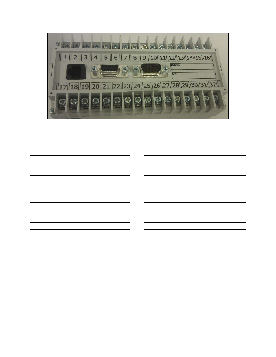
Figure 1 - Instrument Terminals
shows the function of each terminal.
Terminal
Function
Terminal
Function
1
24VDC (COM)
17
EVENT IN 0
2
24VDC (+)
18
EVENT IN 1
3
RS485 RT (-)
19
EVENT IN 2
4
RS485 RT (+)
20
EVENT IN 3
5
SLAVE 1 RS485 (-)
21
EVENT IN COM
6
SLAVE 1 RS485 (+)
22
SLAVE 2 RS485 (+)
7
RELAY COMMON
23
SLAVE 2 RS485 (-)
8
EVENT RELAY 0
24
Not assigned
9
EVENT RELAY 1
25
Not assigned
10
EVENT RELAY 2
26
Not assigned
11
EVENT RELAY 3
27
Not assigned
12
EVENT RELAY 4
28
Not assigned
13
EVENT RELAY 5
29
Not assigned
14
EVENT RELAY 6
30
Not assigned
15
ALARM RELAY NC
31
Not assigned
16
ALARM RELAY NO
32
Not assigned
Table 2 - Terminal List and Functions
Terminals 1 and 2 are used for powering the instrument. Terminals 3 and 4 are used to
connect the instrument as a slave device to a 92XX controller. Terminals 5 and 6 are
used to slave a second 9015 instrument to the first from the second 9015’s terminals 3
and 4.