Vd a-5 – Thinklogical VDA Manual User Manual
Page 12
V D A S e r i e s D V I S p l i t t e r s , R e v . C , M a y , 2 0 1 4
Page 9
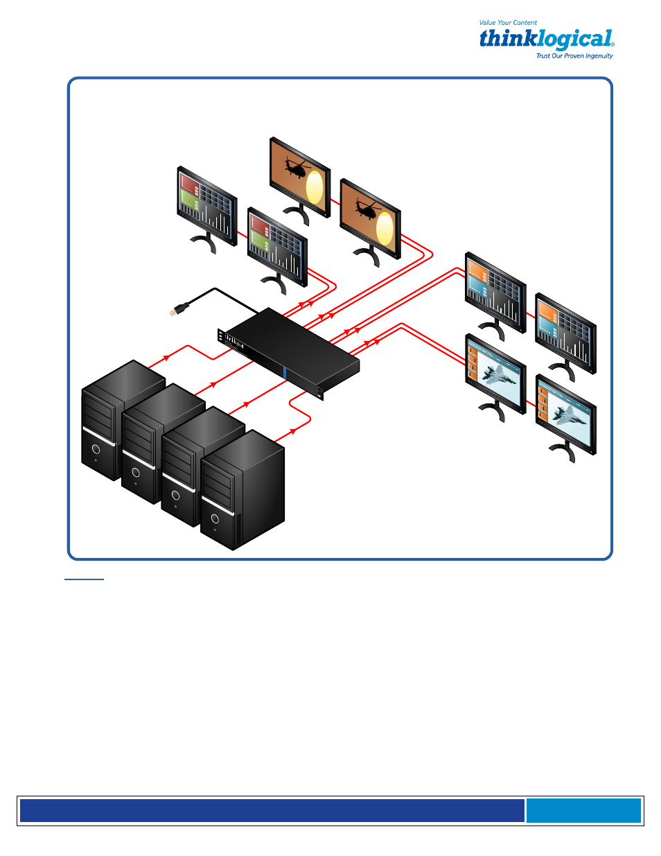
VDA-5 (4x SL 1:2)
4 splitters per chassis each distribute a Single-Link DVI
video source to two Single-Link DVI displays.
4 D
VI S
our
ces
DV
I In
VA
C
DV
I O
ut
VD
A-5
(4 s
plitt
ers
in 1
ch
ass
is)
DV
I O
ut B
ank
1
DV
I O
ut B
ank
2
DV
I O
ut B
ank
4
DV
I O
ut B
ank
3
VDA-5: (4 splitters in 1 chassis)
1.
Connect a Single-Link DVI-D male to male cable from DVI Monitor 1 to the DVI OUT 1
DDC connector on Bank 1 of the VDA Splitter’s rear panel. Connect a Single-Link DVI-
D male to male cable from Output Monitor 2 to the DVI 2 connector of Bank 1. Three
additional pairs of DVI displays can be connected in the same manner to Banks 2, 3
and 4. Turn the monitors on.
2.
Connect the supplied Single-Link DVI-D male to male cable to the video source (DVI-D
video card) and to the DVI IN connector on the VDA Splitter, Bank 1. Three additional
DVI sources can be connected in the same manner to the inputs of Banks 2, 3 and 4.
3.
Ensure that the unit’s ON/OFF switch, located on the rear panel, is in the OFF
position. Connect the AC line cord (PWR-000006-R) to the AC input located on the
rear panel of the chassis and plug it into a standard AC source. Turn the switch ON.
Ensure all video output displays are functioning properly.