Gas or electric heat, Sample wiring diagrams, Page 11 – Venstar T1100REC User Manual
Page 12
Advertising
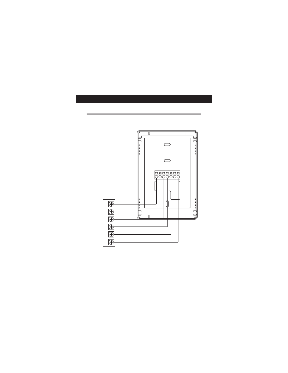
Sample Wiring Diagrams
W2
Y2
R
O
W1
B
Y1
G
C
Gas or Electric Heat
POWER
R
COMPRESSOR
Y
W
GAS VALVE
or
STRIP HEAT
COMMON
C
FAN
G
6 Wire, 1 Stage Cooling, 2 Stage Heat
Residential & Commercial 1 Stage Cooling,
with 2 Stage Gas or Electric Heat.*
2nd STAGE
HEATING
W
2
* If using first stage electric heat, the “EH” dip switch must be
set to ON (see page 5).
Page 11
Advertising