Heat pump, Sample wiring diagrams, Page 13 – Venstar T1100REC User Manual
Page 14
Advertising
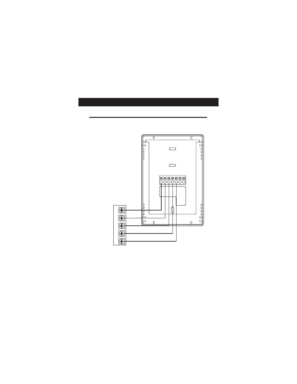
Sample Wiring Diagrams
W2
Y2
R
O
W1
B
Y1
G
C
* The “HP” dip switch must be set to ON (see page 5).
** The “O/B” dip switch must be set to O or B (see page 5).
POWER
R
COMPRESSOR
Y
REVERSING VALVE**
COMMON
C
FAN
G
Heat Pump
5 Wire, 1 Stage Cooling, 1 Stage Heat, Heat Pump* with O or B reversing valve**.
Residential Heat Pumps, split systems & package units, with no auxiliary heat.
O
/B
Page 13
Advertising