Getting started – Westermo MRD-350 User Manual
Page 16
16
6623-2221
Getting started
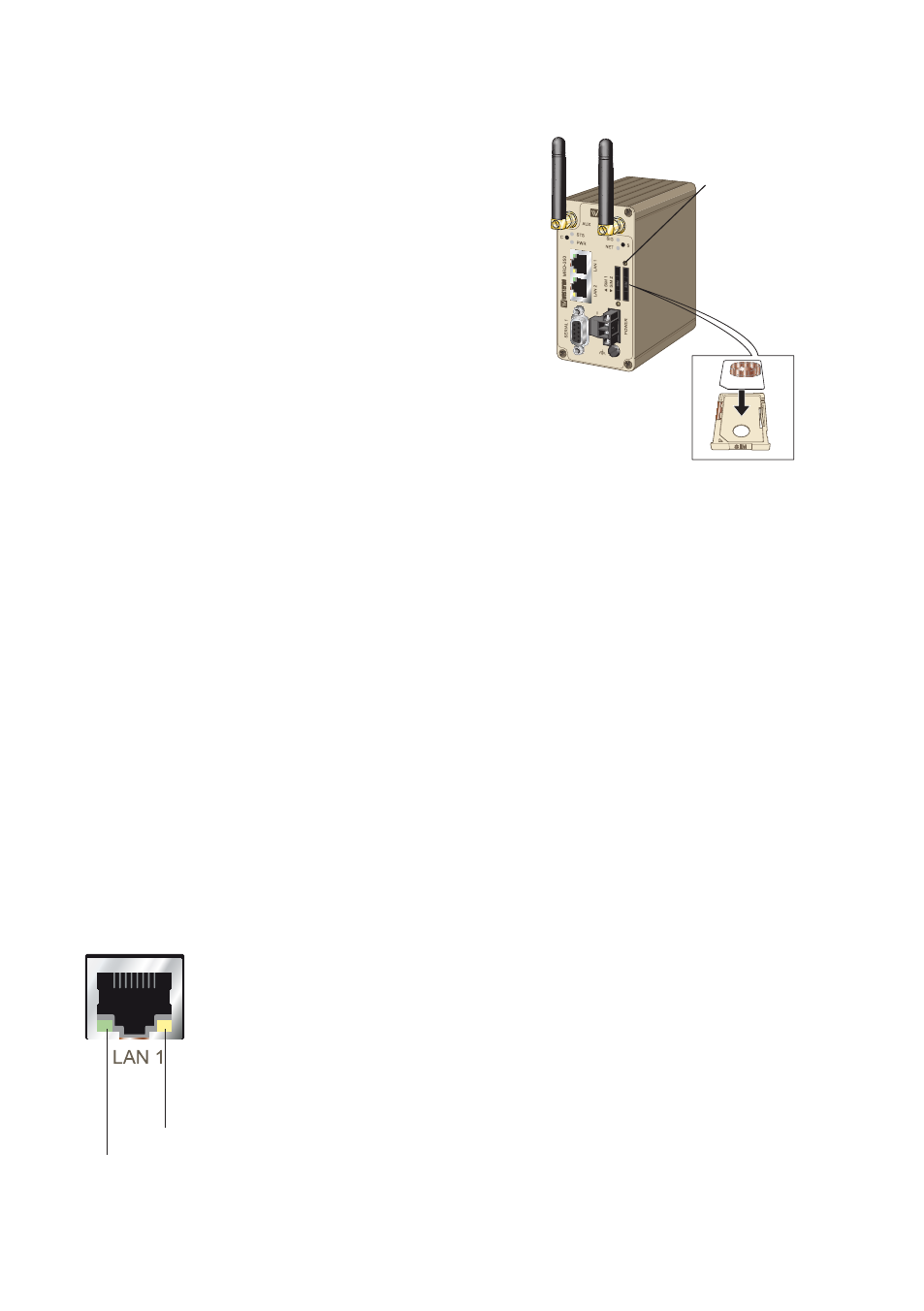
Installing the SIM Card
The SIM card is accessed from the rear of the unit.
To eject the SIM card drawer press the SIM card
…
eject button using a suitable tool and remove
the drawer, refer to figure for the location of
the SIM card eject button.
Insert the SIM card into the SIM card drawer
…
with the contacts facing up, let chambered
corners align.
Slid the drawer back into the unit ensuring that
…
it locks into place.
Note: Before removing or inserting the SIM card,
ensure that the power has been turned off
and the power connector has been removed from the MRD-350.
Connecting the Antenna
The unit has two antenna connectors (SMA). Please ensure that the connecting nut is
done up tightly in order to make a good connection.
Connect the Power Supply
The MRD-350 requires a DC power source in the voltage range of 10 to 60 VDC.
The unit is designed to self protect from permanent damage if the voltage exceeds
60 VDC or if reverse polarity is applied. The router may need to be returned for service
if this occurs. The router can also be damaged if there is any potential difference between
the chassis-ground, RS-232 signal ground, power (–) input, or antenna shield. Before con-
necting any wiring, ensure all components are earthed to a common ground point. An
external isolator will be required if a positive earth power supply is used.
Ethernet
The Ethernet ports are on the front of the unit and are marked LAN 1 and LAN 2, each
port has a LED indicating the connection speed and a LED indicating activity as shown
in figure below. Both ports are capable of auto-negotiation, meaning cross-over cables
are not required. The Ethernet ports are switched, allowing more than one
Ethernet device to be connected to the unit at one time.
Activity LED
Connection speed LED
SIM card drawer
eject button