Controls and components – Allmand Nite-Lite Pro Vertical Tower V Series User Manual
Page 22
22
22
NOTE:
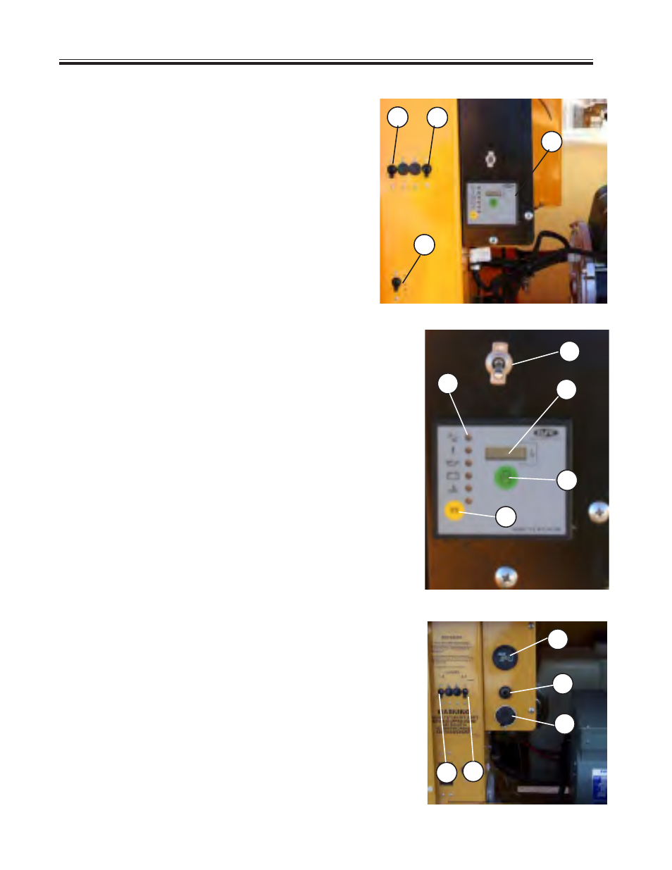
PHOTOGRAPHS MAY SHOW NON-STANDARD EQUIPMENT AND OPTIONS
Fig. 1 Control Panel
FIG. 1. CONTROL PANEL (Kubota)
1. Breaker Switch
Controls lights 1 and 2
2. Breaker Switch
Controls lights 3 and 4
3. Electric Winch On/Off Switch
4. Control Panel (see close up below)
2
1
4
3
1
2
4
3
Fig. 1a Control Panel Close Up
FIG. 1a. CONTROL PANEL (Kubota) CLOSE UP
1. Ignition On switch
Must be in ON position to start engine
2. Engine Start Button
NOTE
: Release button as soon as engine fires.
3. Glow Plug Preheat Button
4. Engine Function Indicator Lights come on
when there is a fault.
5. Hour Meter shows the total elapsed hours
of engine operation
5
FIG. 1b. CONTROL PANEL (CAT)
1. Breaker Switch
Controls lights 1 and 2
2. Breaker Switch
Controls lights 3 and 4
3. Hour Meter
4. Key Switch
5. Glow Plug Indicator
FIG. 1a (CAT)
1
2
3
4
5
CONTROLS AND COMPONENTS