ARAG BRAVO 300S - Multi-row crop sprayers, Direct connection / RCU Installation - Software ver User Manual
Page 15
15
CONTINueS
Boom sprayer
section 2
Boom sprayer
section 3
Boom sprayer
section 4
Boom sprayer
section 1
Valve 1
Valve 3
Valve 2
Valve 4
Boom sprayer
section 5
Valve 5
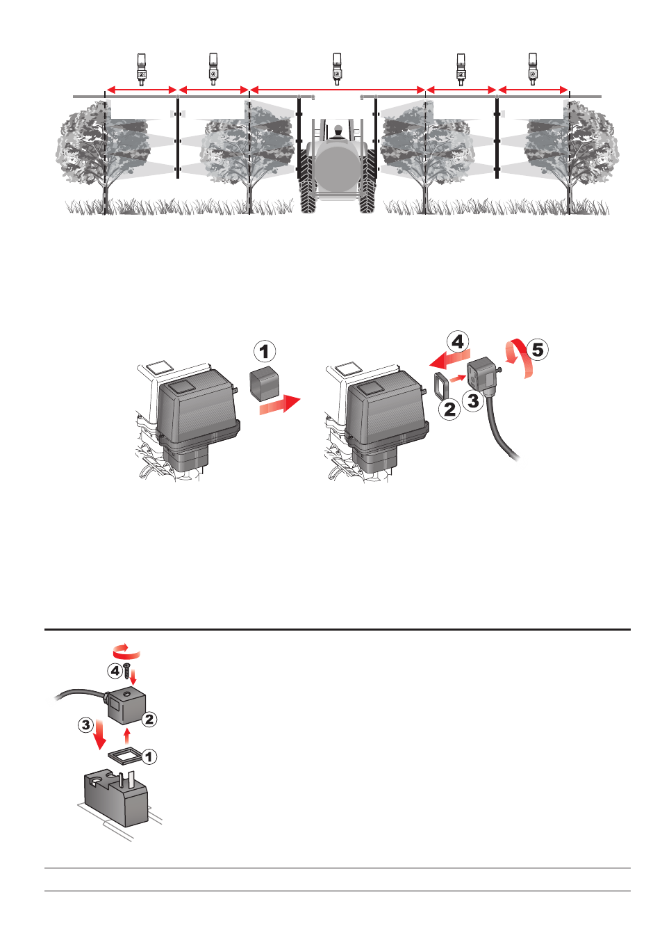
Fig. 11
Connector 1 shall control the valve which in turn is connected to the
boom section 1, and so on
with the other valves.
Connect
"connector 1" to "valve 1", and then the other connectors with increasing numbers from
left to right:
the boom section 1 is the furthest from the machine on the left, looking at the
machine from the rear side (Fig. 11).
Fig. 12
Fix the connectors to the relevant valves according to the initials indicated in your assembly general
diagram (Par. 6.1 - System recommended composition).
• Remove the protection cap (
1, Fig. 12) from the electric valve.
• Place the seal (
2) onto the connector (3) and push the connector fully on (4): be careful not to
bend the contacts upon insertion on the valve.
• Tighten the screw (
5) fully home.
8.4
Hydraulic valves connection
Fig. 13
Bravo 300S can control up to 9 hydraulic functions through double-acting valves.
Fix the connectors to the relevant valves according to the initials indicated in your
assembly general diagram (Par. 6.1 - System recommended composition).
• Position seal (1) onto connector (2) then connect the latter pressing it fully home
(
3): during this operation, take special care not to bend valve electric contacts.
• Insert screw inside connector, and screw it (4) until it is tightened.
The function of each switch on the hydraulic function control panel is described
below.