Figure 4 – H3C Technologies H3C S10500 Series Switches User Manual
Page 8
Advertising
5
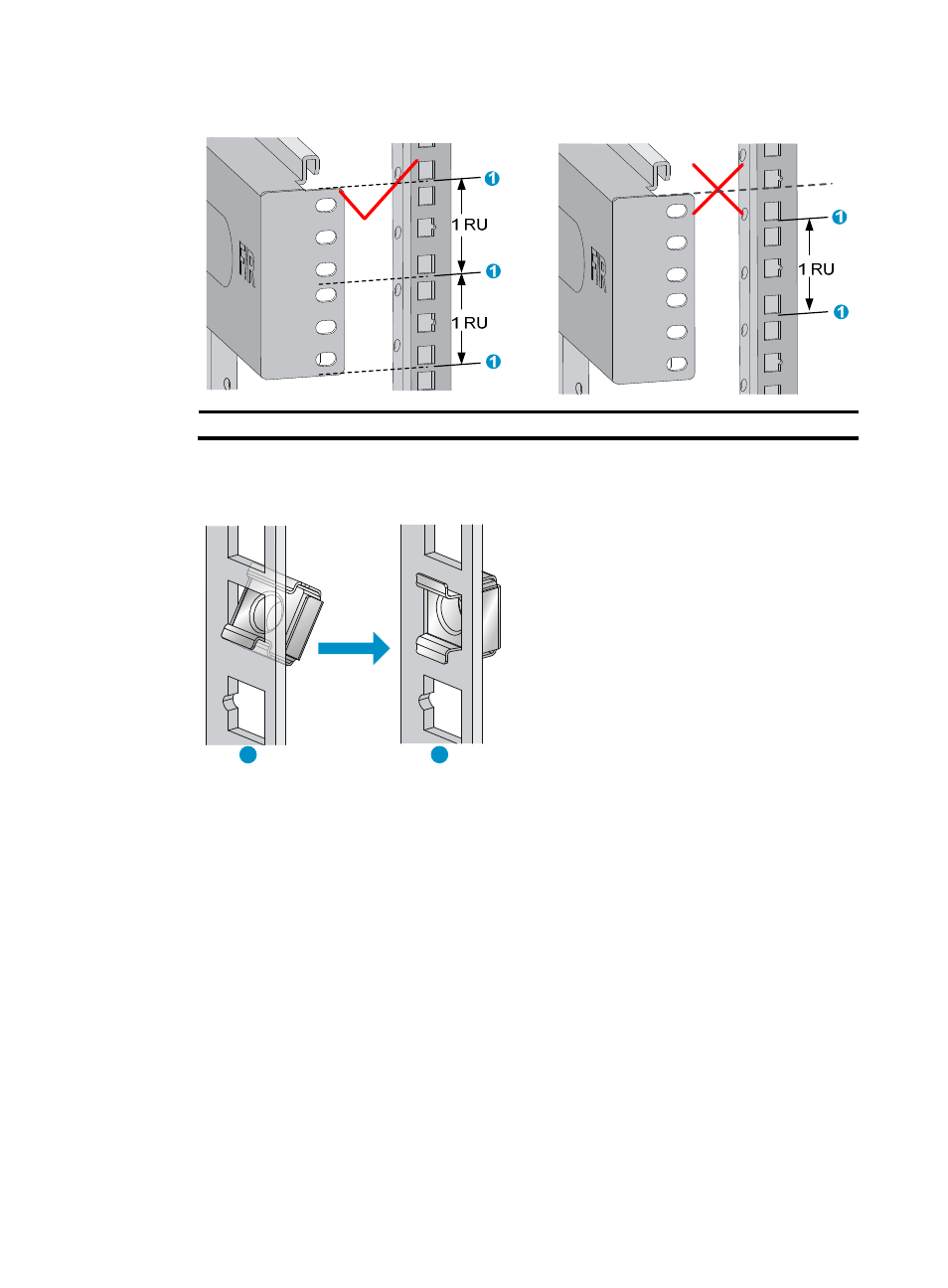
Figure 4 Determining the cage nut installation holes by using a slide rail
(1) Middle of the narrower metal area between holes
3.
Install six cage nuts in the square holes in each rack post, as shown in
Figure 5 Installing a cage nut
4.
Align the installation holes on the front end of a slide rail with the cage nuts on a front rack post,
and use six screws to attach the slide rail to the front rack post.
uses the right slide rail as
an example.
1
2
Advertising
This manual is related to the following products: