Backbone area and virtual links – H3C Technologies H3C S7500E Series Switches User Manual
Page 73
4-4
In addition, as the topology of a large network is prone to changes, enormous OSPF packets may be
created, reducing bandwidth utilization. Each topology change makes all routers perform route
calculation.
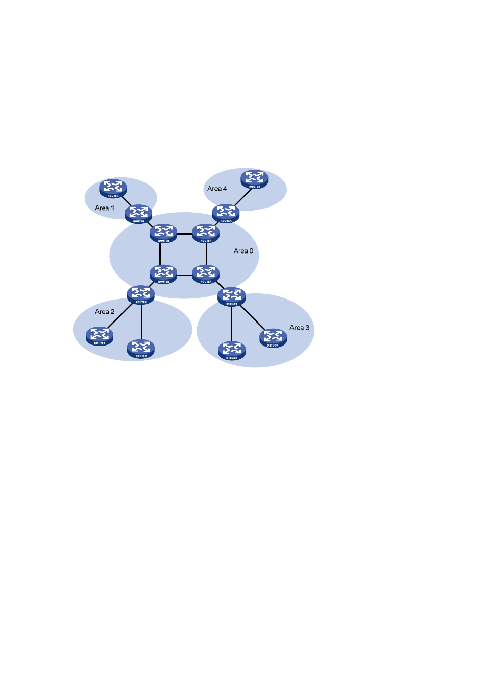
To solve this problem, OSPF splits an AS into multiple areas, which are identified by area ID. The
boundaries between areas are routers rather than links. A network segment (or a link) can only reside
in one area, in other words, an OSPF interface must be specified to belong to its attached area, as
shown in the figure below.
Figure 4-1 OSPF area partition
After area partition, area border routers perform route summarization to reduce the number of LSAs
advertised to other areas and minimize the effect of topology changes.
Backbone area and virtual links
Each AS has a backbone area, which is responsible for distributing routing information between
none-backbone areas. Routing information between non-backbone areas must be forwarded by the
backbone area. Therefore, OSPF requires that:
z
All non-backbone areas must maintain connectivity to the backbone area.
z
The backbone area must maintain connectivity within itself.
In practice, due to physical limitations, the requirements may not be satisfied. In this case, configuring
OSPF virtual links is a solution.
A virtual link is established between two ABRs over a non-backbone area and needs to be configured
on both ABRs to take effect. The non-backbone area is called a “transit area”.
In the following figure, Area 2 has no direct physical link to the backbone area 0. Configuring a virtual
link between ABRs can connect Area 2 to the backbone area.