Configuration procedure – H3C Technologies H3C S5820V2 Series Switches User Manual
Page 19
13
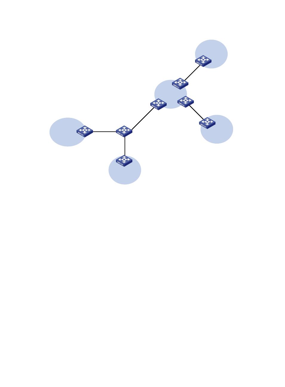
Figure 4 Network diagram
Configuration procedure
Assume that the system name of the MCE device is MCE, the system names of the edge devices of VPN
1 and VPN 2 are VR1 and VR2 respectively, and the system name of PE 1 is PE1.
1.
Configure the VPN instances on the MCE and PE 1.
# On the MCE, configure VPN instances vpn1 and vpn2, and specify an RD and route targets for
each VPN instance.
<MCE> system-view
[MCE] ip vpn-instance vpn1
[MCE-vpn-instance-vpn1] route-distinguisher 10:1
[MCE-vpn-instance-vpn1] vpn-target 10:1
[MCE-vpn-instance-vpn1] quit
[MCE] ip vpn-instance vpn2
[MCE-vpn-instance-vpn2] route-distinguisher 20:1
[MCE-vpn-instance-vpn2] vpn-target 20:1
[MCE-vpn-instance-vpn2] quit
# Create VLAN 10, add port Ten-GigabitEthernet 1/0/1 to VLAN 10, and create VLAN-interface
10.
[MCE] vlan 10
[MCE-vlan10] port Ten-GigabitEthernet 1/0/1
[MCE-vlan10] quit
[MCE] interface vlan-interface 10
# Bind VLAN-interface 10 with VPN instance vpn1, and configure an IP address for
VLAN-interface 10.
CE 2
VPN 1
Site 2
CE 1
VPN 2
Site 1
PE 1
PE 3
PE 2
VPN 2
192.168.10.0/24
VR 2
VPN 1
192.168.0.0/24
VR 1
MCE
XGE1/0/1
Vlan-int10
10.214.10.3/24
XGE1/0/1
Vlan-int30: 30.1.1.2/24
Vlan-int40: 40.1.1.2/24
XGE1/0/3
Vlan-int30: 30.1.1.1/24
Vlan-int40: 40.1.1.1/24
XGE1/0/2
Vlan-int20
10.214.20.3/24