Wlan auto-ap configuration example (on an ac), Network requirements, Configuration procedure – H3C Technologies H3C MSR 50 User Manual
Page 28
1-27
[AC] wlan radio enable all
WLAN Auto-AP Configuration Example (On an AC)
Network requirements
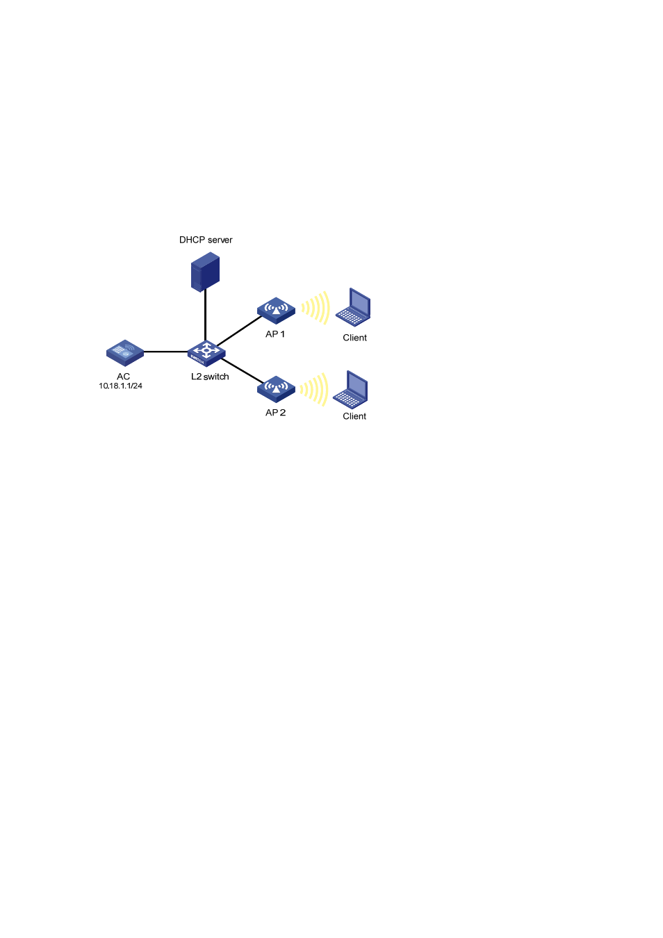
As shown in the following figure, an AC is connected to a Layer 2 switch. AP1 (serial ID SZ001) and
AP2 (serial ID SZ002) are connected to the AC through the L2 switch. AP1, AP2 and the AC are in the
same network. AP1 and AP2 get their IP address from the DHCP server. It is required to enable the
auto-AP function to enable APs to automatically connect to the AC.
Figure 1-18 WLAN service configuration
Configuration procedure
# Create a WLAN ESS interface.
<AC> system-view
[AC] interface WLAN-ESS 1
[AC-WLAN-ESS1] quit
# Define a WLAN service template and bind the WLAN-ESS interface to this service template.
[AC] wlan service-template 1 clear
[AC-wlan-st-1] ssid abc
[AC-wlan-st-1] bind WLAN-ESS 1
[AC-wlan-st-1] authentication-method open-system
[AC-wlan-st-1] service-template enable
[AC-wlan-st-1] quit
# Configure a radio policy (the default radio policy default_rp will be used if you don’t want to configure
a new radio policy for customizing related parameters).
[AC] wlan radio-policy radpolicy1
[AC-wlan-rp-radpolicy1] beacon-interval 200
[AC-wlan-rp-radpolicy1] dtim 4
[AC-wlan-rp-radpolicy1] rts-threshold 2300
[AC-wlan-rp-radpolicy1] fragment-threshold 2200
[AC-wlan-rp-radpolicy1] short-retry threshold 6
[AC-wlan-rp-radpolicy1] long-retry threshold 5
[AC-wlan-rp-radpolicy1] max-rx-duration 500