Local onboard module configuration, D module configuration, Because it is the highest – Grass Valley 8920ADC v.2.0.1A User Manual
Page 18
18
8920ADC Instruction Manual
Configuration
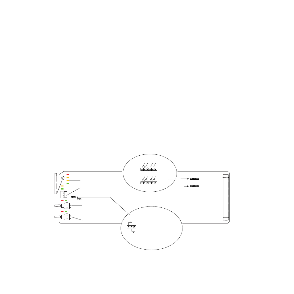
Local Onboard Module Configuration
The 8920ADC module can be configured locally to set parameters using the
jumpers, the rotary switch and two toggle switches shown in
CONF LED indicates status of the configuration process.
These components perform the following:
•
Jumper JP7 – sets control mode for Local only or Remote and Local.
•
Jumpers JP5 and JP6 – set coarse input level adjustment for left and
right channels as explained in
Setting Maximum Operating Level
).
•
SW2 and SW3 (toggle) switches – provide fine adjustment of the left
and right channel input levels as described in
.
•
Function (rotary) switch – selects a desired output configuration (0
through 9, A through F), although not all positions are used.
•
CONF (configuring) LED – when on, indicates the module is initial-
izing or processing configuration information.
Note
Function switch positions 0 and F (Factory defaults) can be used to return the
module configuration to the original factory settings.
Figure 5. Module Configuration Switches and LEDs
SW2 – Left In Level
SW3 – Right In Level
CONF (yellow)
0595_05r1
JP7
LOCAL –
REMOTE –
jumper across these pins
(1 – 2) locks out remote control
jumper across these pins
(2 – 3) enables remote
and local control
Remote Control Lockout
JP5
Pins
Pins
JP5
JP7
JP6
JP6
Coarse Level Setting
1-2 2-3 4-5 5-6
1-2 2-3 4-5 5-6
1
3
SW1 – Function Rotary Switch