Gpi input structure – Grass Valley Kayak HD Installation v.6.8.8 User Manual
Page 60
Advertising
60
Kayak HD — Installation and Service Manual
Section 2 — Installation
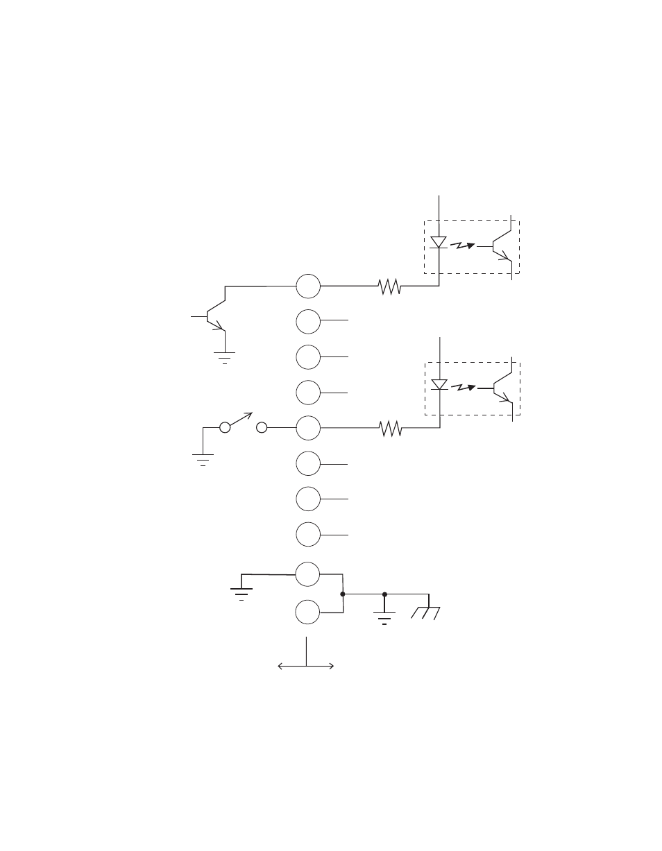
To activate a GPI In you must provide switch closure between a particular
GPI In pin and one of the two GPI In Com pins (Pins 1 and 34).
GPI Input Structure
Figure 35. GPI Input Connections (Typical 2 of 8 connections)
Pins 1 and 34 of each of the two (four) connectors are connected to ground.
For applications that span across more than one connector, only one
ground (common) connection is required.
50-pin Connector
Pin Numbers
Opto Isolator
(1 of 8)
GPI 1
GPI 5
+ 3.3 V
Open
Collector
18
35
19
36
20
4
1
34
3
2
150 ohm
Opto Isolator
(5 of 8)
Ground and
Chassis
Kayak HD Frame
User Equipment
+ 3.3 V
150 ohm
8448_08
r0
Advertising