Power supply, Introduction – Grass Valley NV8256-Plus v.1.2 User Manual
Page 16
6
Rev 1.2 • 20 Oct 08
2. Introduction
Power Supply
tion of each type of card, see
on page 15. The two connected routers are listed as
Router 1 and Router 2. Although the examples list a full complement of input cards, the number of
cards installed depends on the number of inputs and outputs being managed by a specific switching
configuration. The optional, redundant crosspoint card (installed in the center crosspoint card slot)
is not included in the following examples. Only required crosspoint cards are listed.
Power Supply
The power supply for the NV8256-Plus is an external, separate frame, the NV6257. The NV6257
uses the NVISION PS6000 series power supply module. The NV8256-Plus router requires four
PS6000 power supply modules. For redundancy, an additional four PS6000 modules can be
installed. The NV6257 can house a total of four primary and four redundant PS6000 power supply
modules. This means that one NV6257 power supply frame can power one NV8256-Plus router
frame.
The PS6000 power supply module accepts a wide range of AC input voltages and produces five
+48 VDC outputs. The power supply automatically senses the AC input voltage (90–130 and 180–
250 VAC) and adjusts to maintain a relatively constant DC output; no voltage selection is required.
The five regulated outputs are directed to modules in the router where on-board regulators produce
the DC voltages required by the local circuits. Each +48VDC output powers one of the five green
LEDs and output test points located on the front of the power supply. Under normal operation, all
five LEDs are lit. For more information, see
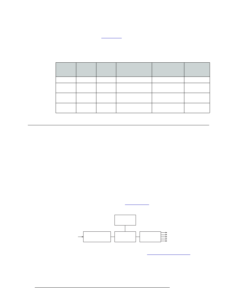
Figure 2-1 shows the power supply architecture.
Figure 2-1. PS6000 Power Supply Module Diagram
For information on making power supply connections, see
Inputs ×
Outputs
Number of
Frames
Number of
Crosspoint
Cards
Crosspoint
Card Slot
Type of
Input Card
Output Cards
in Router
256×256
1
1
Left
Standard
Router 1
256×512
2
2
Router 1: Left
Router 2: Right
Router 1: Standard
Router 2: Filler
Router 1,
Router 2
512×256
2
2
Router 1: Left, Right
Router 2: None
Router 1: Standard
Router 2: Standard
Only on
Router 1
512×512
2
4
Router 1: Left, Right
Router 2: Left, Right
Router 1: Standard
Router 2: Standard
Router 1,
Router 2
Power Sense
and Limiting
AC Input, Fuse,
Rectifiers, and Filter
Power Factor
Correction
+48VDC
Regulators (×5)
+48VDC
Out (×5)
90130VAC or
180250VAC In