Serial control connections, Installation – Grass Valley NV8256-Plus v.1.2 User Manual
Page 48
38
Rev 1.2 • 20 Oct 08
3. Installation
Making Router Control System Connections
In order for the router control system to communicate with the router, Comm port and Baud rate
information must be entered in each control card using UniConfig. This information is entered
using a temporary diagnostic connection between the router and UniConfig. (See
on page 43.) After the information is entered, the router control system con-
nections can “see” the router and the router control system connections can be configured.
Serial Control Connections
Serial control connections are used to connect a router to the router control system. Serial connec-
tions are often used for third-party control systems. Although serial connections can be used for the
NVISION NV9000 control system, it is recommended that an Ethernet connection is used instead.
(See
The serial control ports are divided into two sets that communicate with the primary control card or
the secondary control card. Additional ports enable you to connect to an alternate control system
(i.e., backup system) or to set up dual control, if desired. For a detailed description of the serial con-
trol connections, see
In order for the router to communicate with the router control system through a serial connection,
Comm port and Baud rate settings need to be set in the control card.
Serial control connections use SMPTE 207M DE9 connectors and serial (RS-422/485) cable.
How to Make Serial Control Connections
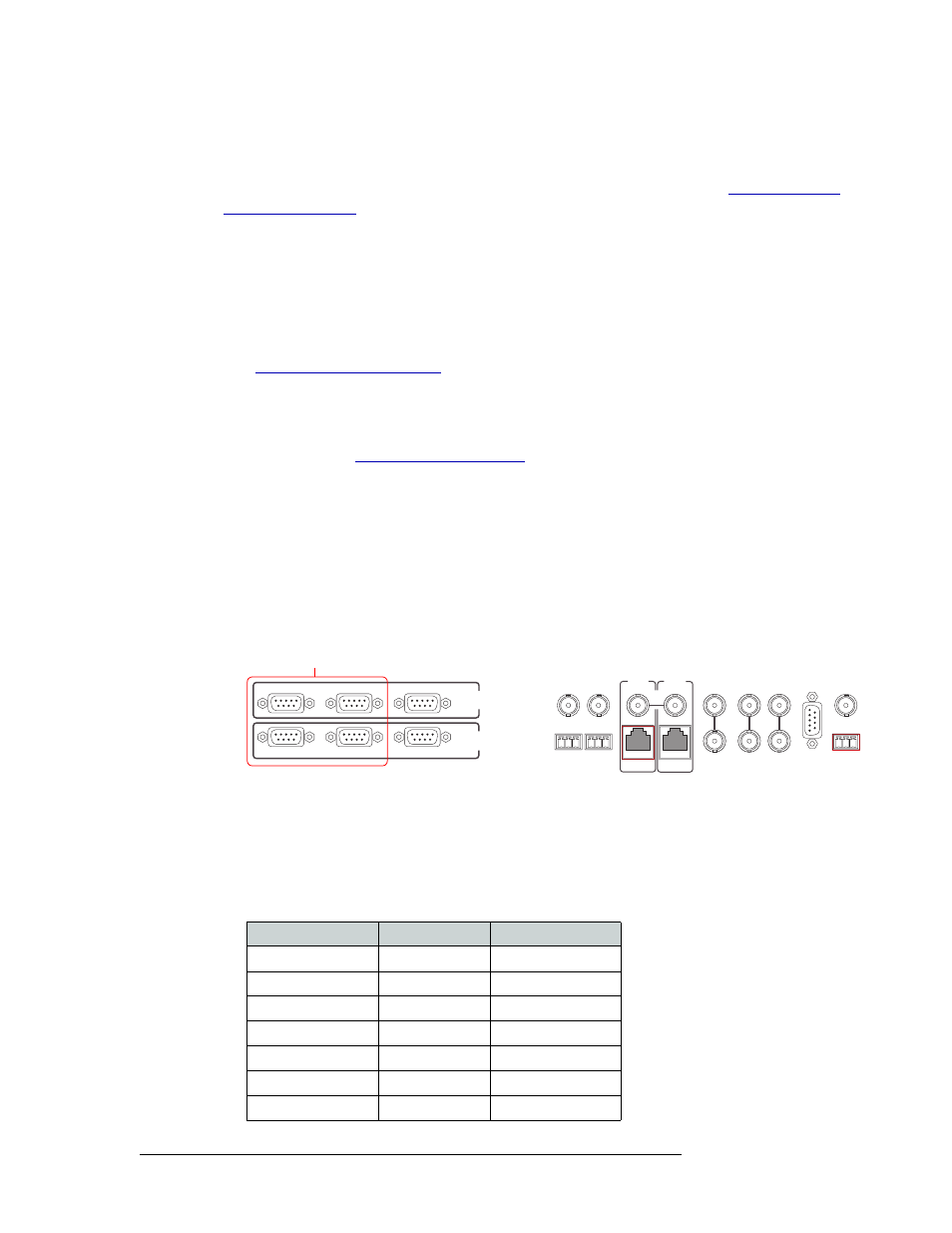
1 Locate the serial control connections on the rear of the router, as shown in Figure 3-8. Serial
control connections are labeled ‘PRIMARY CONTROL’ for the primary control card and
‘SECONDARY CONTROL’ for the secondary control card.
Figure 3-8. Serial Connections to Router Control System (Rear View)
2 Connect to the ‘CTRL 1’ connection in the ‘PRIMARY CONTROL’ section using a DE9 con-
nector and serial cable.
3 Connect the other end of the serial cable to the (primary) router control system using a DE9
connector.
The following lists the pin wiring for the DE9 connectors:
CTRL 1
CTRL 2
DIAG
CTRL 1
CTRL 2
DIAG
SECONDARY
CONTROL
PRIMARY
CONTROL
SEC
CTRL
PRI
CTRL
AES
REF 1
AES
REF 2
LOOP
THRU
10 B 2
10/100 BT
10 B 2
10/100 BT
VIDEO
REF 2
VIDEO
REF 1
ALARMS
TIME
CODE
NVISION
AUX BUS
LOOP
LOOP
LOOP
Serial Connections to Control System
Control End
Pins
Router End
Ground
1 ------------1
Ground
Rx–
2 ------------2
Tx–
Tx+
3 ------------3
Rx+
Tx Common
4 ------------4
Rx Common
N/C
5 ------------5
N/C
Rx Common
6 ------------6
Tx Common
Rx+
7 ------------7
Tx+