Rear connections, System connections, Rear connections system connections – Grass Valley NV8256-Plus v.1.2 User Manual
Page 20: Introduction
10
Rev 1.2 • 20 Oct 08
2. Introduction
Module Slots and Rear Connections
Rear Connections
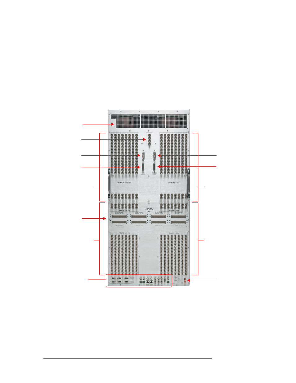
The rear of the NV8256-Plus (Figure 2-4 on page 10) features a backplate containing BNC connec-
tions: 256 for receiving signals and 256 for distributing signals. These connections are passive and
pass the signals through to active, receiving connections on the input cards and output cards.
An additional set of four BNC connections, located in the upper, center area of the frame, send sig-
nals to the monitor card. In the lower region of the frame are connections for system and power
functions, as shown in Figure 2-5 on page 11. In the center of the frame are connections for expan-
sion cables used to send signals between two connected NV8256-Plus router frames. In Figure 2-4
on page 10, the expansion connections are shown with the cover plates still on.
Figure 2-4. NV8256-Plus Router (Rear View)
System Connections
The NV8256-Plus features connections for managing system functions, located on the rear of the
router. These connections enable you to connect to:
• A router control system using either serial, Ethernet, or GSC Node Bus connectors.
• A stable source of video signal for reference purposes.
• The UniConfig application, installed on a PC, used to perform configuration tasks.
Output
Connectors
(128)
Fan Exhaust
Monitor
Connectors
Power Conn. 1
Power Supply
Monitor
Expansion
Connectors
Ground Lug
Power Conn. 2
Output
Connectors
(128)
Input
Connectors
(128)
Remote Redundant
Crosspoint Control
Input
Connectors
(128)
System
Connectors