Operation, Setting redundant crosspoint card switching, Replace xpt (1–256) – Grass Valley NV8256-Plus v.1.2 User Manual
Page 65: Standby mode, Remote control
NV8256-Plus Digital Video Router • User’s Guide
55
4. Operation
Setting Redundant Crosspoint Card Switching
How to Set Redundant Crosspoint Card Operations
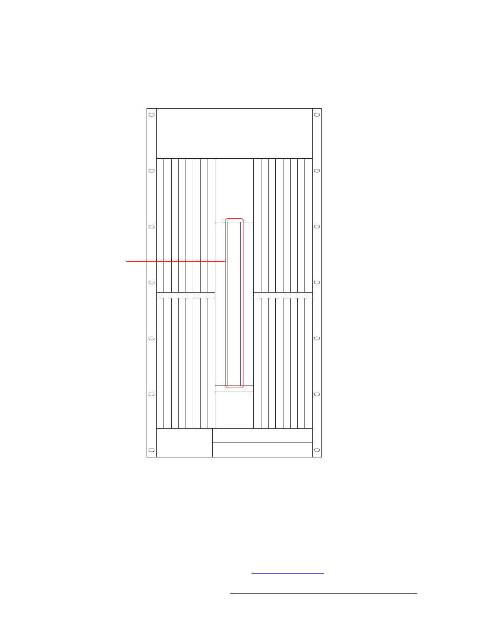
1 Facing the front of the router with the door open, locate the redundant crosspoint card, as shown
Figure 4-1. Location of Redundant Crosspoint Card (Front View)
2 The front panel buttons should be lit. Press a button to activate that function:
•
Replace XPT (1–256)
—
take over active control of inputs 1–256 from the local crosspoint
card installed in the left crosspoint card slot.
•
Standby Mode
—
sets redundant card to act as a backup to the local crosspoint card should
the card fail.
•
Replace XPT (257–512)
—
take over active control of inputs 257–512 from the crosspoint
card installed in the right crosspoint card slot.
•
Remote Control
—
allows external remote control of the redundant crosspoint card. For
information on remote control, see
, following.
Control CardPrimary
OUTPUTS 129-144
OUTPUTS 145-160
OUTPUTS 161-176
OUTPUTS 177-192
OUTPUTS 193-208
OUTPUTS 209-224
OUTPUTS 225-240
OUTPUTS 241-256
INPUTS 129144
INPUTS 145160
INPUTS 161176
INPUTS 177192
INPUTS 193208
INPUTS 209224
INPUTS 225240
INPUTS 241256
OUTPUTS 116
OUTPUTS 1732
OUTPUTS 3348
OUTPUTS 4964
OUTPUTS 6580
OUTPUTS 8196
OUTPUTS 971
12
OUTPUTS 1
13128
INPUTS 116
INPUTS 1732
INPUTS 3348
INPUTS 4964
INPUTS 6580
INPUTS 8196
INPUTS 971
12
INPUTS 1
13128
MONIT
OR
FAN
CROSSPOINT
INPUTS 1-256
CROSSPOINT
(REDUNDANT)
CROSSPOINT
INPUTS 257-512
Control CardSecondary
Redundant
Crosspoint
(Middle
Card Slot)