Installing active cards, Les slots, see, Installation – Grass Valley NV8256-Plus v.1.2 User Manual
Page 42
32
Rev 1.2 • 20 Oct 08
3. Installation
Installing Active Cards
9 Facing the rear of the NV6257, connect power cords from an AC power source (90–230 VAC,
50–60 Hz) into power connections PS 1 through PS 8, as shown in Figure 3-1 on page 30. You
must connect one power cord for each PS6000 power supply module installed. (See step 10.)
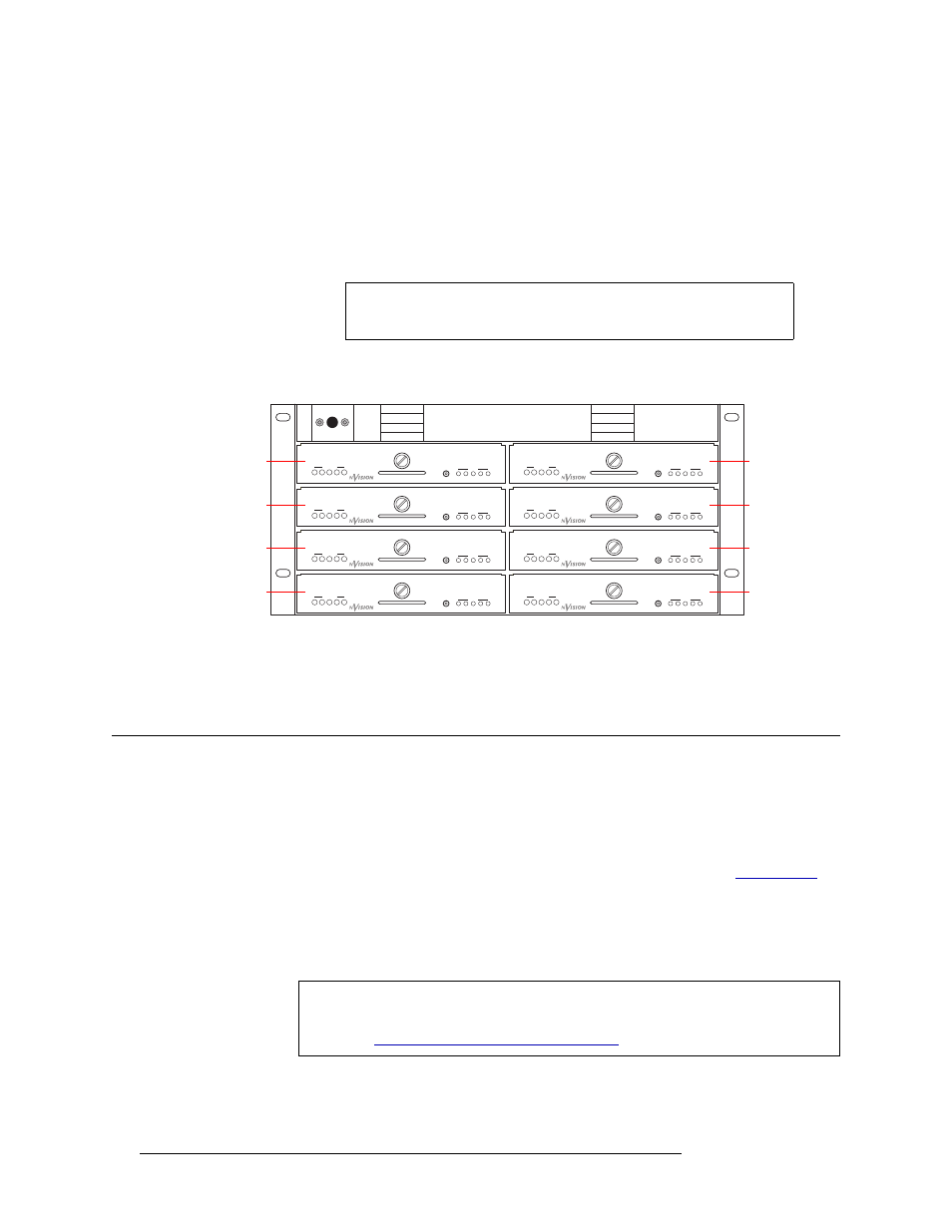
10 Install the PS6000 power supply modules as follows:
a Facing the front of the NV6257, install the primary PS6000 power supply modules in slots
PS 1, PS 3, PS 5 and PS 7, as shown in Figure 3-3.
b (Optional) Facing the front of the NV6257, install the redundant PS6000 power supply
modules in slots PS 2, PS 4, PS 6 and PS 8, as shown in Figure 3-3.
Figure 3-3. NV6257 Power Supply (Front View)
11 Facing the rear of the router, connect the ground lug to ground using a copper wire from 14 to 6
AWG. The ground lug is located in the lower, right-hand corner of the frame.
Installing Active Cards
The NV8256-Plus router features several active cards that manage incoming signals, forwarding of
control system commands, signal switching, and distribution of outgoing signals. Cards slide into a
card guide such that the connectors on the rear of the card interface with the motherboard. Each
card has two levers—one at the top and one at the bottom—that help insert the card into place for
installation and eject the card for easy removal. For a description of each card, see
All cards can be inserted and removed with the power on.
How to Install Active Cards:
1 Locate the slots for the control, input, output, crosspoint and monitor cards, as shown in
Note
The NV6257 fan is powered by slot PS 1 or PS 2. A PS6000 power
supply module must be installed in one of these slots.
PS5
PS6
PS7
PS8
PS1
PS2
PS3
PS4
GND
POWER
1
2
3
4
5
1
2
3
4
5
+
48V
PS6000
GND
POWER
1
2
3
4
5
1
2
3
4
5
+
48V
PS6000
GND
POWER
1
2
3
4
5
1
2
3
4
5
+
48V
PS6000
GND
POWER
1
2
3
4
5
1
2
3
4
5
+
48V
PS6000
GND
POWER
1
2
3
4
5
1
2
3
4
5
+
48V
PS6000
GND
POWER
1
2
3
4
5
1
2
3
4
5
+
48V
PS6000
GND
POWER
1
2
3
4
5
1
2
3
4
5
+
48V
PS6000
GND
POWER
1
2
3
4
5
1
2
3
4
5
+
48V
PS6000
POWER
POWER
POWER
POWER
POWER
POWER
POWER
POWER
GND
GND
GND
GND
GND
GND
GND
GND
Primary PS (1)
Redundant PS (2)
Primary PS (3)
Redundant PS (4)
Primary PS (5)
Redundant PS (6)
Primary PS (7)
Redundant PS (8)
Caution
Do not drop, roughly handle, or stack circuit boards. If a board does not easily
remove or insert, stop installation activities and contact NVISION Technical Sup-
port. (See