Rear connections (hardware version only), Using the control panel – Grass Valley NV9601 v.2.0 User Manual
Page 27
NV9601 Control Panel • User’s Guide
17
2. Using the Control Panel
Rear Connections (Hardware Version Only)
Rear Connections (Hardware Version Only)
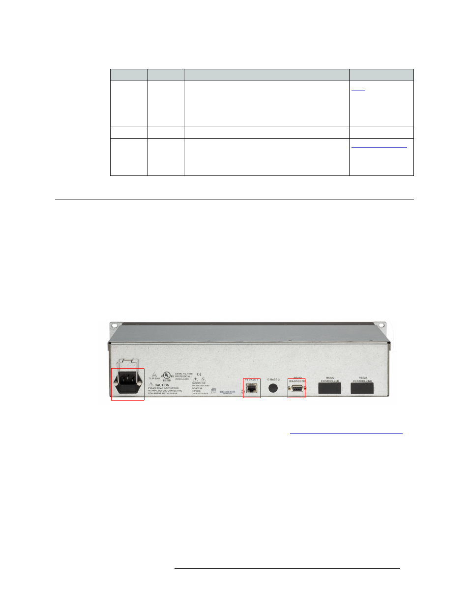
The rear of the NV9601 has three connections:
• Power
—
One IEC connection to an AC power source (90-130/180-250
VAC, 50/60
Hz).
• Ethernet
—
One ‘10 Base T’ connection to connect the control panel to an Ethernet switch. This
enables the control panel to be part of a network and connected to a computer running the con-
figuration application (NV9000-SE Utilities) and a controller (such as the NV9000).
• Diagnostic
—
One ‘RS232 Diagnostic’ DB9 connection for performing diagnostics. This is
reserved for Miranda use only.
Figure 2-9 shows the rear connections:
Figure 2-9. NV9601 (Rear)
For instructions on connecting to the rear connections, see
Setting Up the Control Panel for Use
Take
XY, MD
Switches the selected preset source device(s) to the
selected destination device on all levels that have a preset
loaded. The ‘Status’ column in the display area lists the
new device(s).
The default button legend is Take.
Undefined
—
An undefined button cannot be used and remains unlit.
XY / MD
Mode
XY, MD
Switches the panel between X-Y and multi-destination
modes. The button is green for X-Y mode and amber for
multi-destination mode.
The default button legend is XY MD.
Button
Mode
Description
Related Topic
Power
Ethernet
Diagnostic