Grass Valley UniConfi NVISION Series v.2.0 User Manual
Page 161
151
UniConfig
User’s Guide
Complete the settings in this page and click ‘Next’ at the bottom of the window. The third
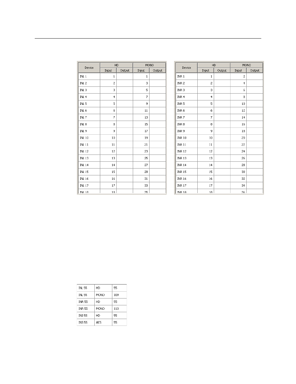
and final window appears, in which is displayed a table of the devices that will be created:
The table shows the ports for each of the virtual levels for each device. Note that the MONO
left inputs start at 1 and increment by 2.
If the proposed result appearing in this window is correct, click ‘Finish’. Otherwise, amend or
cancel your entries.
Later, when you complete the mono right inputs, the MONO right inputs start at 2 and incre-
ment by 2. Thus, left/right pairs proceed (1,2), (3,4) (5,6) and so on.
Perform the same 3-step process for the remaining mono devices. When you process the
second step, be aware of the starting port number for inputs or outputs. The increment for
inputs and outputs is 2 for all mono device sets.
6 When you complete all 6 device sets, you can examine NV9000-SE Utilities’ various tables to
verify your work. This is an excerpt from the ‘PhysConns’ table showing input 55:
A few seconds of scrutiny shows that the stereo input (INS 55) is 55 as expected. The mono
inputs (INL 55, INR 55) are 109 and 110, also as expected and fit the formulas given earlier:
R = S × 2
L = R –
1
“Mono left” Inputs
“Mono right” Inputs