Setting addresses and connecting cables – Grass Valley PFR 500/E Dec 10 2001 User Manual
Page 39
Setting addresses and connecting cables
November 17, 2000
PFC 500/E Instruction Manual
39
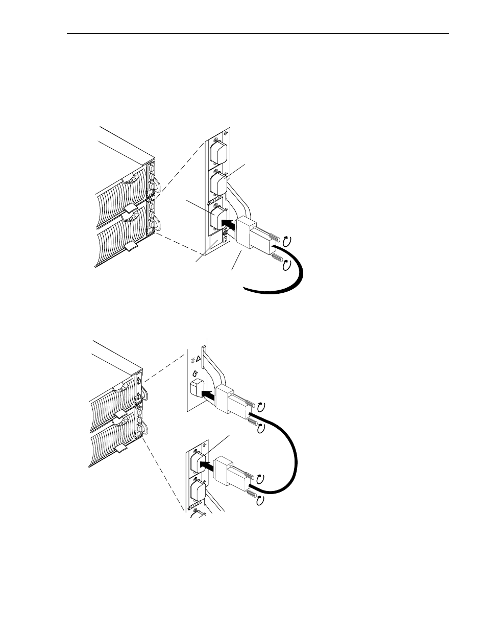
8. Attach the Fibre Channel cable from the Profile XP Media Platform Fibre Channel
Disk board to the RC’s A port. Use a copper cable as shown here
IMPORTANT: Do not leave an unused (that is, dangling) cable connected to an RC
port because it may cause excess noise on the loop.
9. To expand this PFC 500, cable its EXP connector to the corresponding PFC 500E’s
PRI (primary) connector as shown here.
10. If the PFC500 has another RC and PFC 500Es, connect the PFC500’s other RC and
the PFC 500E’s other LCCs as above.
A
B
EXP
A
B
EXP
A
B
EXP
A. Plug the copper cable from the
Profile XP Media Platform Fibre
Channel Disk board into port A on the
RC.
B. Tighten the two screws on each
cable connector.
To server, hub, or other FC device
Port A
Port B
RJ-style connector for
serial connection to an
RCS or a console
A
B
EXP
A
EXP
PRI
IMPORTANT: Do not connect a cable between
an RC in slot A and any LCC in slot B or between
an RC in slot B and any LCC in slot A.
A. Plug one end of the copper cable
onto the expansion (EXP)
connector on the RC in the
PFC500/E.
D. Tighten the two screws on the
cable’s connector.
C. Plug the other end of the copper
cable into the primary (PRI)
connector on the LCC in the
PFC500E.
B. Tighten the two screws on the
cable’s connector.
EXP port