G128 cylinder surface slot milling, 6 sl cy cles – HEIDENHAIN iTNC 530 (340 49x-01) ISO programming User Manual
Page 356
356
8 Programming: Cycles
8.6 SL Cy
cles
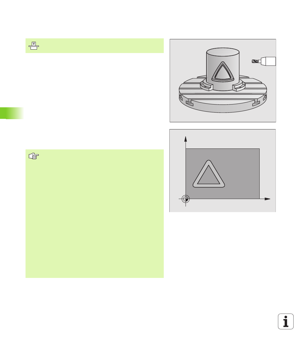
CYLINDER SURFACE slot milling (Cycle G128,
software option 1)
This cycle enables you to program a guide notch in two dimensions
and then transfer it onto a cylindrical surface. Unlike Cycle G127, with
this cycle the TNC adjusts the tool so that, with radius compensation
active, the walls of the slot are always parallel. Program the midpoint
path of the contour together with the tool radius compensation. With
the radius compensation you specify whether the TNC cuts the slot
with climb milling or up-cut milling:
1
The TNC positions the tool over the cutter infeed point.
2
At the first plunging depth, the tool mills along the programmed
slot wall at the milling feed rate Q12 while respecting the finishing
allowance for the side.
3
At the end of the contour, the TNC moves the tool to the opposite
wall and returns to the infeed point.
4
Steps 2 and 3 are repeated until the programmed milling depth Q1
is reached.
5
Then the tool moves to the set-up clearance.
C
Z
Machine and control must be specially prepared by the
machine tool builder for use of this cycle.
Before programming, note the following:
In the first NC block of the contour program, always
program both cylinder surface coordinates.
The memory capacity for programming an SL cycle is
limited. For example, you can program up to 1024 straight-
line blocks in one SL cycle.
The algebraic sign for the cycle parameter DEPTH
determines the working direction. If you program
DEPTH = 0, the cycle will not be executed.
This cycle requires a center-cut end mill (ISO 1641).
The cylinder must be set up centered on the rotary table.
The tool axis must be perpendicular to the rotary table. If
this is not the case, the TNC will generate an error
message.
This cycle can also be used in a tilted working plane.
The TNC checks whether the compensated and non-
compensated tool paths lie within the display range of the
rotary axis, which is defined in Machine Parameter 810.x.
If the error message “Contour programming error” is
output, set MP 810.x = 0.