Defining machining positions, Fundamentals – HEIDENHAIN iTNC 530 (340 49x-02) Pilot User Manual
Page 111
111
Defining
Mach
ining
Posit
io
ns
Defining Machining Positions
Fundamentals
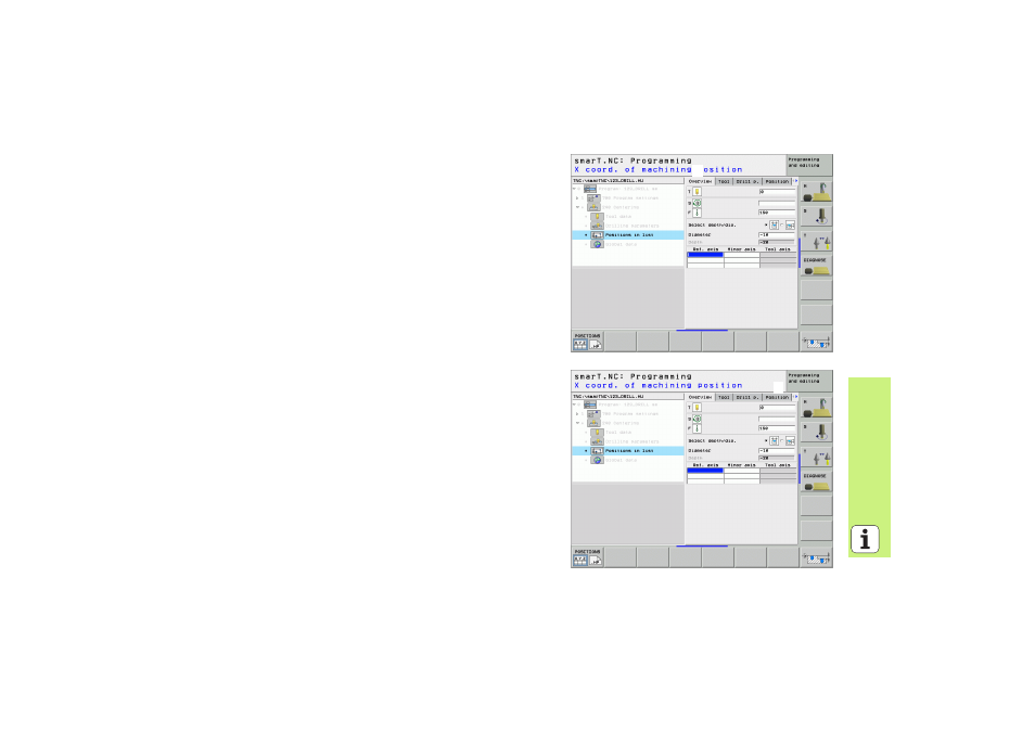
On the overview form (
1
) you can directly define the machining positions
of the current machining step in Cartesian coordinates (see figure at top
right). If the machining is to be performed at more than three positions,
you can define up to six more positions—for a total of nine—on the
Positions detail form (
2
).
Incremental input is allowed beginning with the 2nd machining position.
You can use the I key or soft key to switch over. The first machining
position must be absolute.
The fastest, easiest and most accurate way of defining machining
positions is with the pattern generator. The pattern generator
immediately displays the entered machining positions graphically after
the required parameters have been entered and saved.
smarT.NC automatically saves in a point table (.HP file) the machining
positions you defined using the pattern generator. This point table can be
used as often as you like. A very convenient feature is the possibility of
hiding or disabling any machining positions by graphically selecting them.
Point tables that you may have used on older controls can also be used
with smarT.NC.
1
1
1
2