Selecting and saving a contour, See "selecting and saving a, 1 pr ocessing dxf files (sof tw ar e option) – HEIDENHAIN iTNC 530 (60642x-04) User Manual
Page 282
282
Programming: Data Transfer from DXF Files or Plain-language Contours
7.1 Pr
ocessing DXF files (sof
tw
ar
e option)
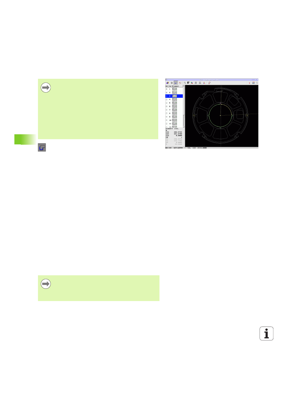
Selecting and saving a contour
Select the mode for choosing a contour. The TNC
hides the layers shown in the left window, and the
right window becomes active for contour selection
In order to select a contour element, hover over the
contour element to be selected with the mouse
pointer. The TNC displays an arrow to indicate the
current machining direction, which you can change on
the contour element by changing the position of the
mouse. Click the desired contour element with the
left mouse button. The selected contour element
turns blue. At the same time, the TNC marks the
selected element with a symbol (circle or line) in the
left window. If further contour elements in the
selected machining sequence are clearly selectable,
these elements turn green. Click on the last green
element to assume all elements into the contour
program. The TNC shows all selected contour
elements in the left window. The TNC displays
elements that are still green in the NC column without
a check mark. The TNC does not save these elements
to the contour program. You can also include the
marked elements in the contour program by clicking
in the left window
If necessary you can also deselect elements that you
already selected, by clicking the element in the right
window again, but this time while pressing the CTRL
key. You can deselect all selected elements by
clicking the recycle bin icon
You must use the touchpad on the TNC keyboard or a
mouse attached via the USB port in order to select a
contour.
If you are not using the contour program in the smarT.NC
operating mode, you must specify the machining
sequence when selecting the contour that it matches the
desired machining direction.
Select the first contour element such that approach
without collision is possible.
If the contour elements are very close to one another, use
the zoom function.
If you have selected polylines, the TNC shows a two-level
ID number in the left window. The first number is the
serial contour element number, the second element is the
element number of the respective polyline from the DXF
file.