Defining a workpiece blank, Orkpiece blank definition (see "defining a, Programming the first part 1.3 – HEIDENHAIN TNC 640 (34059x-02) ISO programming User Manual
Page 49
Programming the first part
1.3
1
TNC 640 | User's Manual for DIN/ISO Programming | 5/2013
49
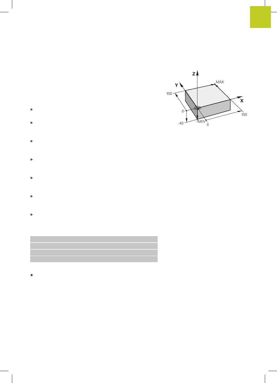
Defining a workpiece blank
Immediately after you have created a new program, the TNC starts
the dialog for entering the workpiece blank definition. Always
define the workpiece blank as a cuboid by entering the MIN and
MAX points, each with reference to the selected reference point.
After you have created a new program, the TNC automatically
initiates the workpiece blank definition and asks for the required
data:
Spindle axis Z – Plane XY: Enter the active spindle axis. G17 is
saved as default setting. Accept with the ENT key
Workpiece blank def.: minimum X: Smallest X coordinate of
the workpiece blank with respect to the reference point, e.g. 0.
Confirm with the ENT key
Workpiece blank def.: minimum Y: Smallest Y coordinate of
the workpiece blank with respect to the reference point, e.g. 0.
Confirm with the ENT key
Workpiece blank def.: minimum Z: Smallest Z coordinate of
the workpiece blank with respect to the reference point, e.g.
–40. Confirm with the ENT key
Workpiece blank def.: maximum X: Largest X coordinate of
the workpiece blank with respect to the reference point, e.g.
100. Confirm with the ENT key
Workpiece blank def.: maximum Y: Largest Y coordinate of
the workpiece blank with respect to the reference point, e.g.
100. Confirm with the ENT key
Workpiece blank def.: maximum Z: Largest Z coordinate of
the workpiece blank with respect to the reference point, e.g. 0.
Confirm with the ENT key. The TNC concludes the dialog
Example NC blocks
%NEW G71 *
N10 G30 G17 X+0 Y+0 Z-40 *
N20 G31 X+100 Y+100 Z+0 *
N99999999 %NEW G71 *
Further information on this topic
Defining the workpiece blank: page 94