11 troubleshooting, Drive-side error codes, Faults – Yaskawa SI-ET3 User Manual
Page 44
44
YASKAWA ELECTRIC SIEP C730600 62B 1000-Series Option SI-ET3 Technical Manual
11 Troubleshooting
11
Troubleshooting
Drive-Side Error Codes
Drive-side error codes appear on the drive digital operator. Causes of the errors and corrective actions are listed in
. For additional error codes that may appear on the drive digital operator, refer to the drive Technical Manual.
Faults
Both bUS (option communication error) and EF0 (External fault input from the option) can appear as an alarm or as a
fault. When a fault occurs, the digital operator ALM LED remains lit. When an alarm occurs, the ALM LED flashes.
If communication stops while the drive is running, use the following questions as a guide to help remedy the fault:
• Is the option properly installed?
• Is the communication line properly connected to the option? Is it loose?
• Is the controller program working? Has the controller/PLC CPU stopped?
• Did a momentary power loss interrupt communications?
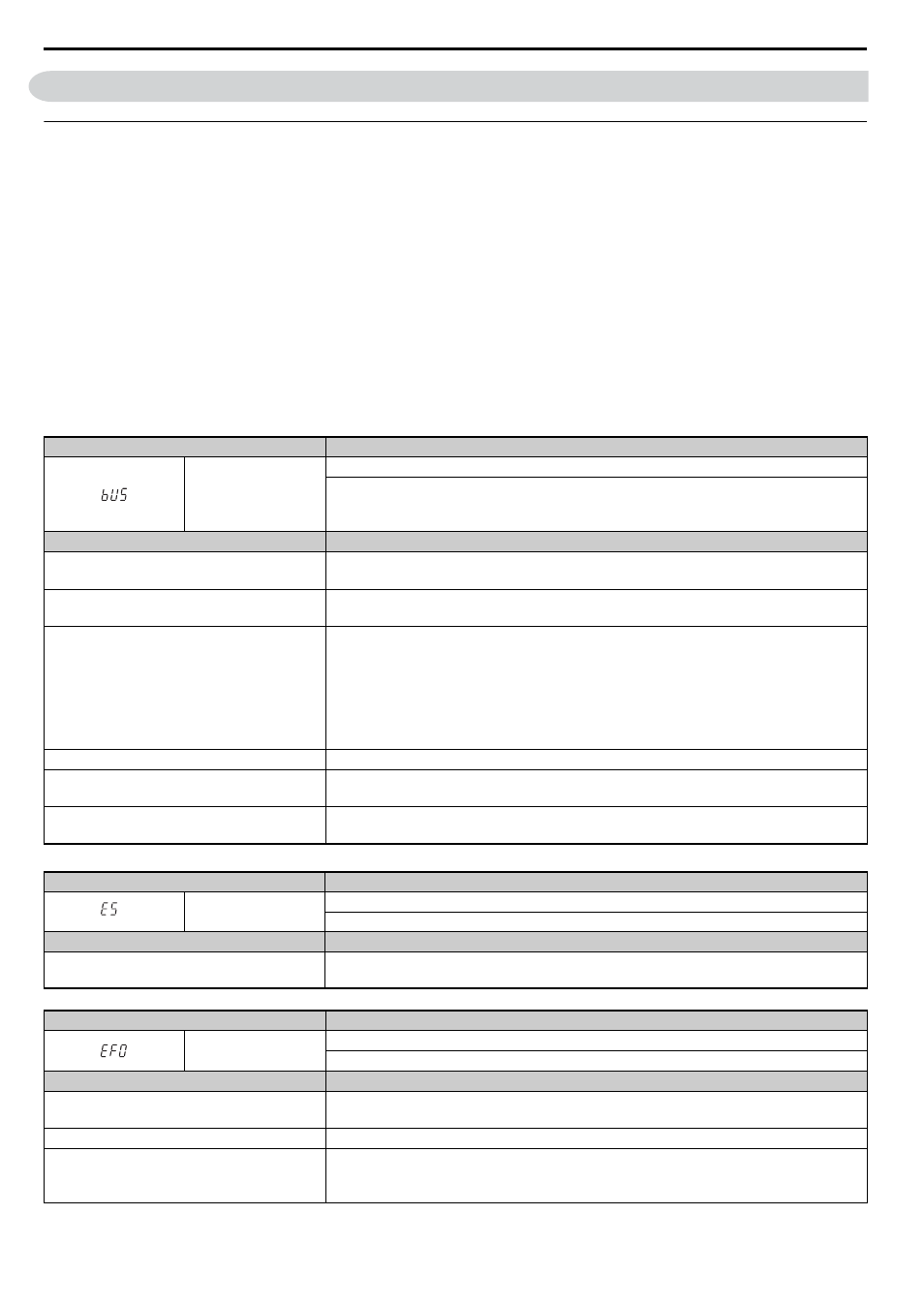
Table 25 Fault Display and Possible Solutions
LED Operator Display
Fault Name
bUS
Option Communication Error
• After establishing initial communication, the connection was lost
• Only detected when the run command or frequency reference is assigned to the option
(b1-01 = 3 or b1-02 = 3)
Cause
Possible Solution
Master controller (PLC) has stopped
communicating
• Check that power is supplied to the PLC
• Check that PLC is not in program mode
Communication cable is not connected properly
• Check for faulty wiring
• Correct any wiring problems
A data error occurred due to electric interference
• Inspect items that can minimize the effects of electrical noise
• Counteract noise in the control circuit, main circuit, and ground wiring
• If a magnetic contactor is identified as a source of noise, install a surge absorber to the
contactor coil
• Make sure the cable used meets the MECHATROLINK-III requirements
• Make sure the option ground wire is connected between option FE terminal and the drive
ground terminal connected to earth ground
Option is damaged
If there are no problems with the wiring and the error continues to occur, replace the option.
Connection Time-out
• The option Requested Packet Interval (RPI) timer timed out
• Make sure that RPI time is set properly
Duplicate Station Address
Check if the option shares Station Address with at least one other node. Check the setting values
of F6-20.
LED Operator Display
Fault Name
E5
MECHATROLINK Watchdog Timer Error
The watchdog has timed out.
Cause
Possible Solution
Data has not been received from the PLC,
triggering the watchdog timer.
⇒ Execute DISCONNECT or ALM_CLR, then issue a CONNECT command or SYNC_SET
command and proceed to phase 3.
LED Operator Display
Fault Name
EF0
Option Card External Fault
The alarm function for an external device has been triggered.
Cause
Corrective Action
An external fault is being sent from the upper
controller (PLC)
• Remove the cause of the external fault
• Reset the external fault input from the PLC device
Problem with the PLC program
Check the program used by the PLC and make the appropriate corrections.
PLC is in the Idle Mode.
• Set the PLC to the Run Mode
• Set the drive parameter F6-54 to 0 (Enabled) not to detect errors while the PLC is in the Idle
Mode