4 terminals, Main circuit terminals, Control terminals, signal levels – Yaskawa VS606 V74X V7 to V1000 User Manual
Page 7: Terminals
PL.V1000-4X.01 Transition Guide 6/22/10
Page 7 of 32
Yaskawa America, Inc.
Product Transition Guide
PL. V1000-4X.01 Rev: 6/22/10
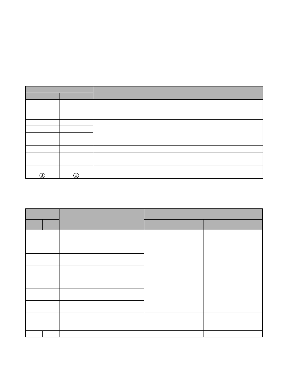
1.4 Terminals
Main Circuit Terminals
As the V74X and V1000-4X may have different terminals sizes (depending on capacity), the terminals must be
carefully checked before replacement (see Section 1-4).
The main terminal functionality has not been changed between the V74X and the V1000-4X drive.
Control Terminals, Signal Levels
The V74X and V1000-4X initial settings for terminal function are shown below.
"—" indicates that an equivalent terminal on the other unit does not exist.
Main Terminals
Note
V74X
V1000-4X
R/L1
R/L1
Power supply connection
S/L2
S/L2
T/L3
T/L3
U/T1
U/T1
Drive output
V/T2
V/T2
W/T3
W/T3
B1
B1
Braking resistor or external braking unit connection
B2
B2
Braking resistor connection
+1
+1
DC Choke connection, DC power supply input
+2
+2
DC Choke connection
—
—
DC power supply input, external braking unit connection
Ground
Control
Terminals
Function
Signal Level
V74X
V1000-
4X
V74X
V1000-4X
S1
Multi-Function input 1
(1: Run forward 0: Stop)
Photocoupler 24 VDC, 8A
isolation
Photocoupler 24 VDC, 8A
S2
Multi-Function input 2
(1: Run reverse 0: Stop)
S3
Multi-Function input 3
(External fault)
S4
Multi-Function input 4
(Fault reset)
S5
Multi-Function input 5
(Multi-step speed 1)
S6
Multi- Function input 6
(Multi-step speed 2)
S7
Multi-Function input 7
(JOG reference)
SC
Multi-Function input common
—
—
RP
Pulse input
(frequency reference)
Frequency range:
1.0~32 kHz
Frequency range:
0.5~32 kHz
FS
+V
Analog input power supply
+12 V (max. current 20 mA)
+10.5 V (max. current 20 mA)