Yaskawa Modbus TCP/IP SI-EM3D/V User Manual
Page 26
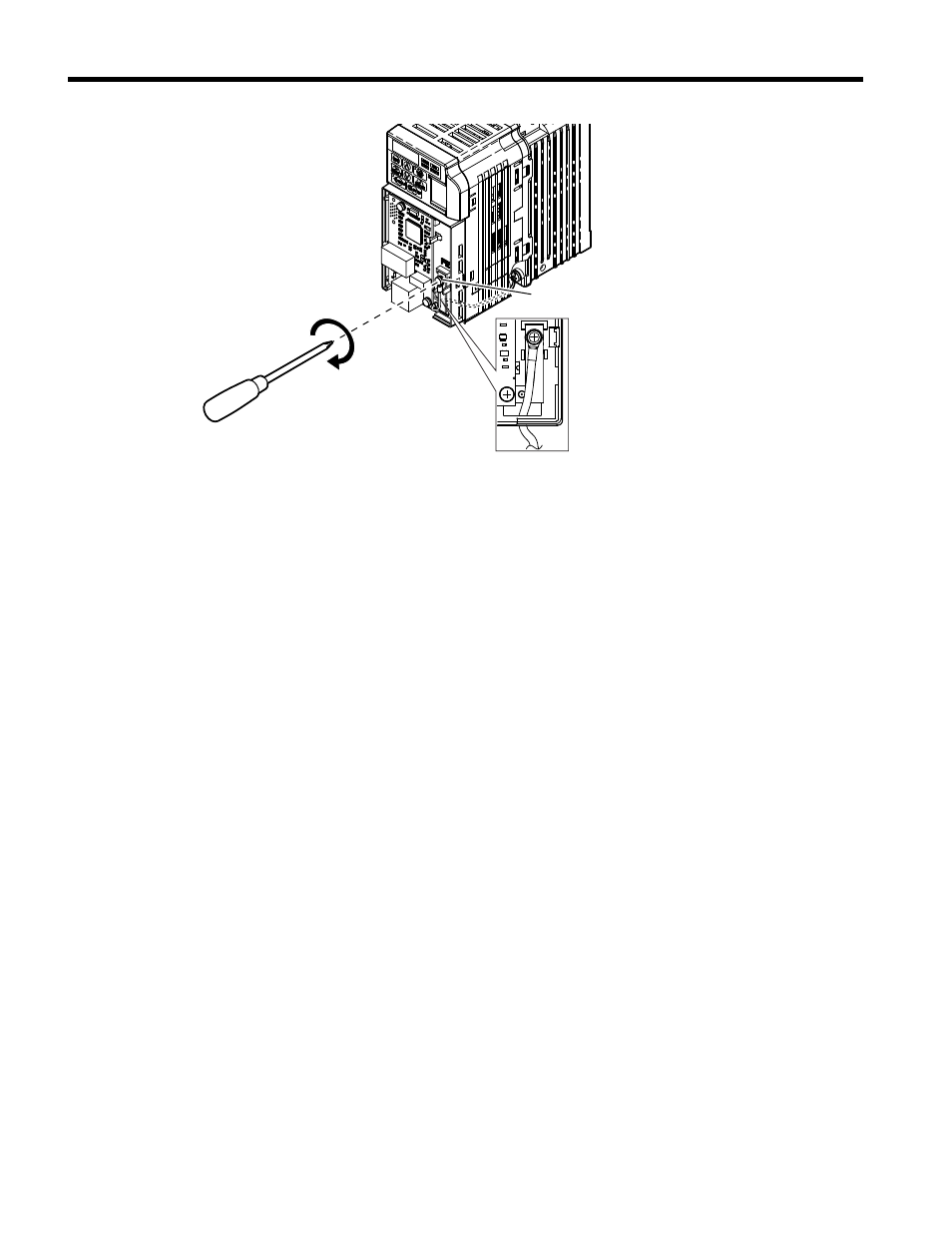
Option ground terminal
Figure 17 Connect the Ground Wire to the Option
14.
Connect the communication cable to the option modular connector (CN1) port 1.
To connect the option to a network, firmly connect RJ45 8-pin shielded twisted pair
Cat5e cable(s) into the modular connector ports (see
).
Communication Cable Specifications
Only use cable recommended for Modbus TCP/IP. Using a cable not specifically
recommended may cause the option or drive to malfunction.
The dual RJ45 network ports on the option board act as a switch to allow for flexibility
in cabling topology. For example, a traditional star network topology may be employed
by using a single port on the option board. Alternatively, a daisy-chained approach
may be employed by using both RJ45 ports. The daisy-chained approach reduces
the requirements of central switch ports. A ring topology is also possible. When
implementing a ring topology, Rapid Spanning Tree Protocol (RSTP) must be enabled
to function correctly.
5 Installation Procedure
26
YASKAWA TOEP YAICOM 17A V1000 Option Dual-Port Modbus TCP/IP SI-EM3D/V Installation Manual