Enter command settings when upgrading the drive, H5-11 and the enter command, 7 modbus tcp/ip messaging – Yaskawa Modbus TCP/IP SI-EM3D/V User Manual
Page 39
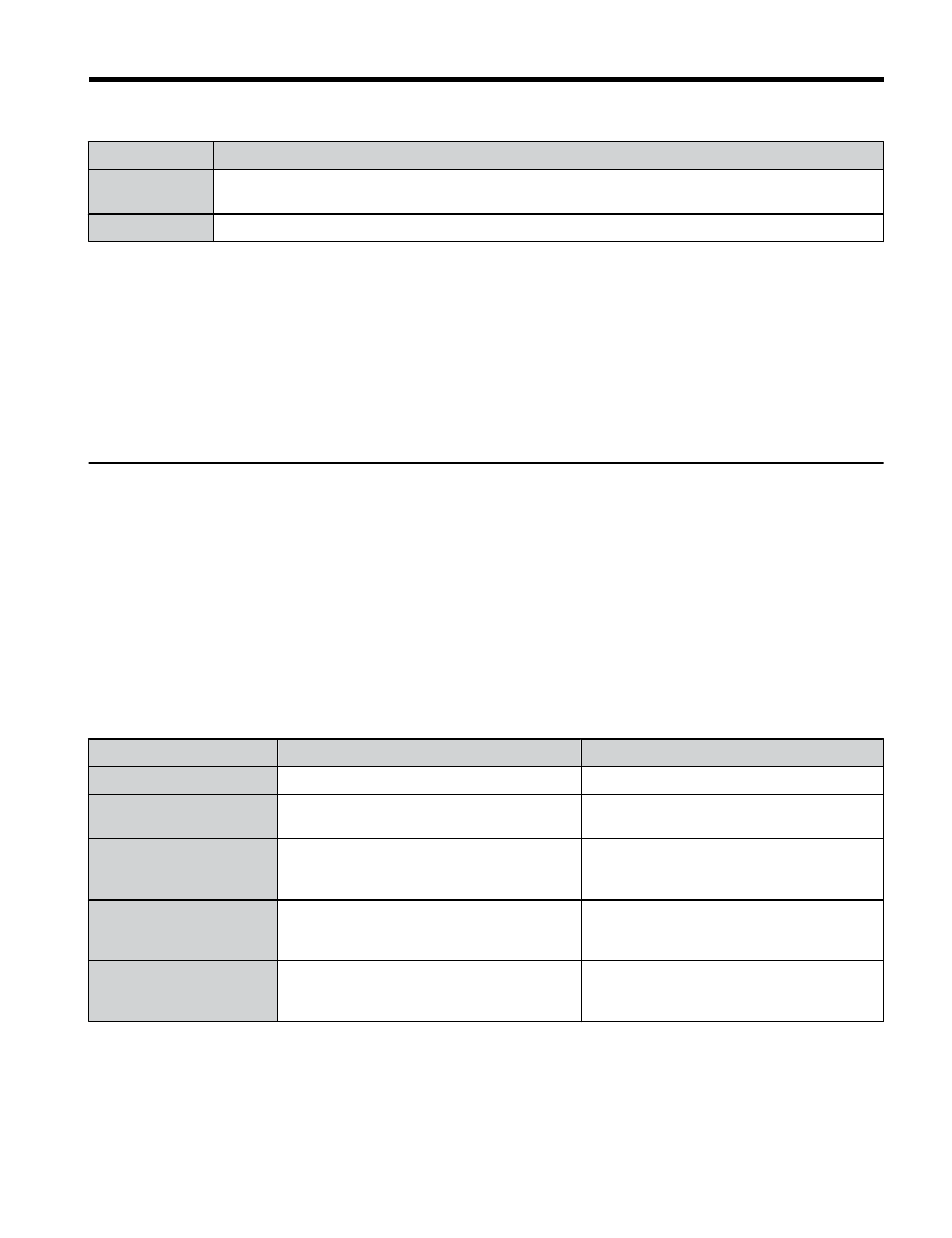
Table 10 Enter Command Types
Register No.
Description
0900H
Writes data into the EEPROM (non-volatile memory) of the drive and enables the data in RAM at
the same time. Parameter changes remain even if the power supply is cycled.
0910H
Writes data in the RAM only. Parameter changes are lost when the drive is shut off.
Note:
1. Because the EEPROM can be written to a maximum of 100,000 times, refrain from writing to the
EEPROM too often. The Enter command registers are write-only. Consequently, if these registers
are read, then the register address will be invalid (Error code: 02H). An Enter command is not required
if reference or broadcast data are sent to the drive.
2. Parameter data cannot be written to EEPROM during undervoltage, even using 0900H.
3. If undervoltage occurs when a making several parameter changes issued with a single ENTER
command, the writing process may be aborted before all of the new changes have been written.
Because all of the data has not yet been written, the EEPROM data error “CPF06” will be displayed
the next time power to the drive is cycled. To prevent this problem, wait approximately 5 seconds
after issuing the ENTER command before shutting off drive power.
u
Enter Command Settings when Upgrading the Drive
When replacing earlier Yaskawa drive models with a V1000 and keeping the MEMOBUS/
Modbus communications settings, parameter H5-11 needs to be set in accordance with how
the Enter command functions in the older drive. H5-11 determines if an Enter command is
needed to activate parameter changes in the drive.
• Set parameter H5-11 to 0 when upgrading from a G7 or F7 series drive to V1000-Series
drive.
• Set parameter H5-11 to 1 when upgrading from a V7 series drive to V1000-Series drive.
n
H5-11 and the Enter Command
H5-11 Settings
H5-11 = 0
H5-11 = 1
Drive being replaced
G7, F7
V7
How parameter settings
are enabled
When the Enter command is received from
the master.
As soon as the value is changed.
Upper/lower limit check
Upper/lower limit check is performed taking
the settings of related parameters into
account.
The upper/lower limit of the changed
parameter is checked only.
Default value of related
parameters
Not affected. The settings of related
parameters remain unchanged. They must
be changed manually if needed.
The default settings of related parameters
are changed automatically.
Error handling when
setting multiple
parameters
Data is accepted even if one setting is
invalid. The invalid setting will be
discarded. No error message occurs.
Error occurs if only one setting is invalid.
All data sent are discarded.
7 Modbus TCP/IP Messaging
YASKAWA TOEP YAICOM 17A V1000 Option Dual-Port Modbus TCP/IP SI-EM3D/V Installation Manual
39