Enter command types – Yaskawa Modbus TCP/IP SI-EM3D/V User Manual
Page 38
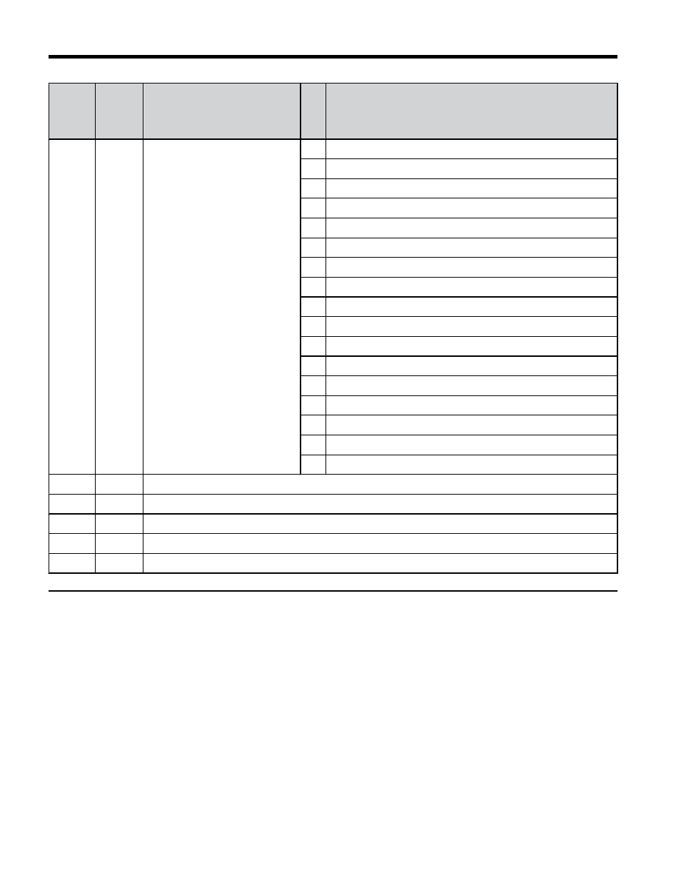
Addre
ss
(hex)
Drive
Regist
er
(hex)
Description
Bit
Description
200B
C2
Error Signal 3
0
MEMOBUS/Modbus Communication Error (CE)
1
Option Communication Error (bUS)
2
Reserved
3
Reserved
4
Control Fault (CF)
5
Zero Servo Fault (SvE)
5
Reserved
6
Option External Fault (EF0)
7
PID Feedback Loss (FbL)
8
Undertorque Detection 1 (UL3)
9
UL4 Undertorque Detection 2 (UL4)
A
High Slip Braking Overload (oL7)
B
Reserved
C
Reserved
D
Reserved
E
Reserved
F
Hardware Fault (includes oFo)
200C
4E
Terminal A1 Input Level Monitor (U1-13)
200D
49
Digital Input Terminal Status (U1-10)
200E
50
Terminal A3 Input Level Monitor (U1-15)
200F
F1
PG Count Channel 2
2010
4D
Drive Software Number (Flash) (U1-25)
u
Enter Command Types
The drive supports two types of Enter commands as shown in
. An Enter command
is enabled by writing 0 to register number 0900H or 0910H. These registers can be written to
only. An error will occur if the user attempts to read from these registers.
7 Modbus TCP/IP Messaging
38
YASKAWA TOEP YAICOM 17A V1000 Option Dual-Port Modbus TCP/IP SI-EM3D/V Installation Manual