506/p5 – Yaskawa GPD505 User Manual
Page 5
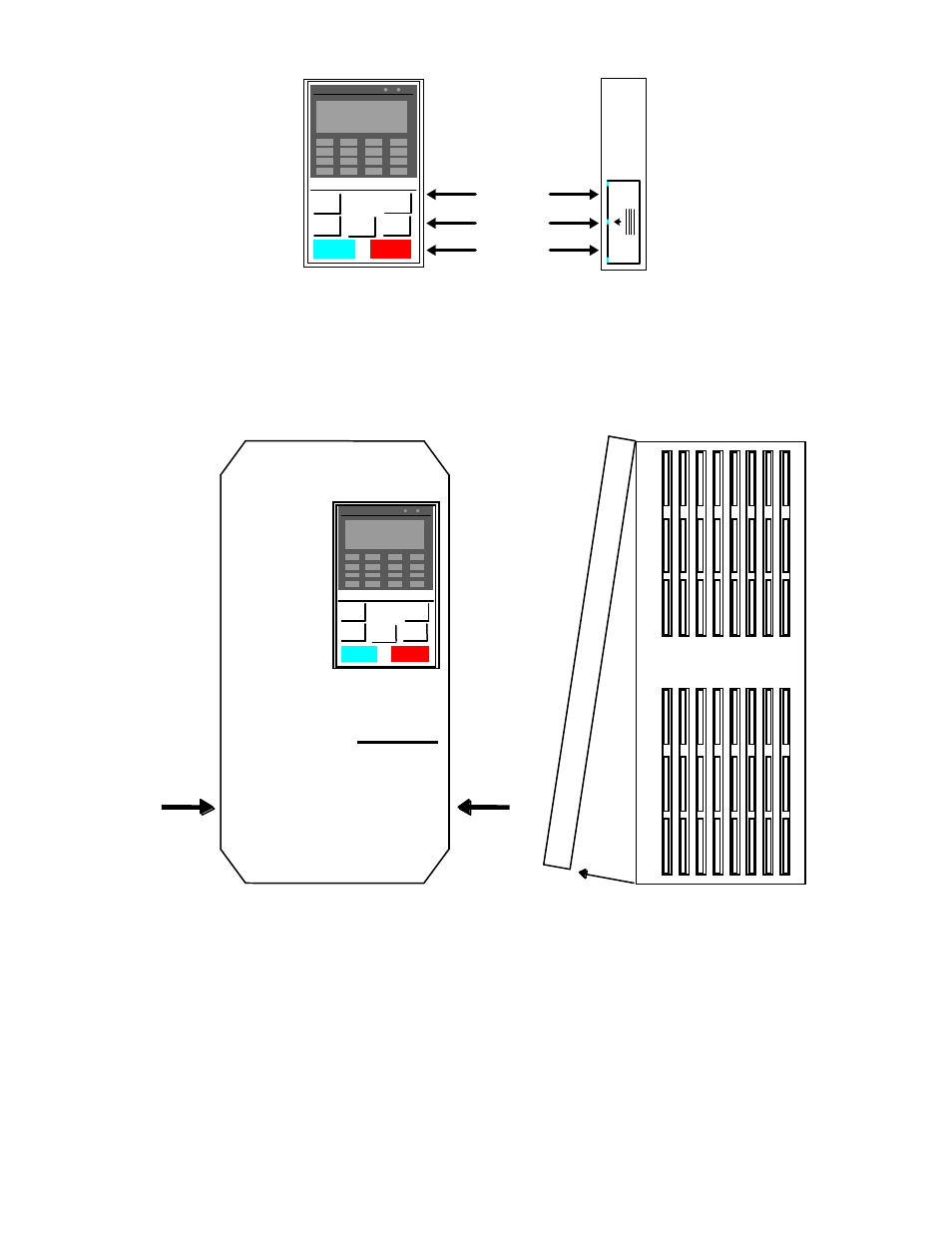
Locking
Plate
Figure 2. Operator Removal
Step 2.
Remove the drive cover, applying pressure to the locking tabs on either side of the cover as
illustrated in Figure 3. With the locking tabs disengaged, pivot the cover out from the bottom.
Continue pivoting it until the top hinge disengages.
GPD
506/P5
Press
Press
Figure 3. Cover Removal
Step 3.
Position the option card so that the 12-pin interface cable is to the left, as illustrated in Figure 4.
Carefully press the attached cable connector into connector 2CN until it is firmly seated.
Please note the orientation of the locking tab relative to the connector mounted on the control
board.
Step 4.
Position the option board mounting holes directly over the four standoffs on the control board.
Carefully press the option board onto the standoffs until it is firmly seated.
TM4028
7/12/2001
5