Parameters a - 31, Stall prevention, Table a.1 f7 parameter list (continued) – Yaskawa F7 Drive User Manual User Manual
Page 196
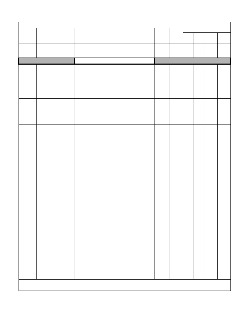
Parameters A - 31
L2-08
Frequency Reduction Gain at
KEB Start
KEB Frequency
Sets the percentage of output frequency reduction at the beginning
of deceleration when a KEB command is input from multi-function
input.
Reduction = slip frequency before KEB operation
× L2-08 × 2
0 to 300
100%
A
A
A
A
Stall Prevention
L3-01
Stall Prevention Selection
During Accel
StallP Accel Sel
Selects the stall prevention method used to prevent excessive
current during acceleration.
0: Disabled - Motor accelerates at active acceleration rate. The
motor may stall if load is too heavy or accel time is too short.
1: General Purpose - When output current exceeds L3-02 level,
acceleration stops. Acceleration will continue when the output
current level falls below the L3-02 level.
2: Intelligent - The active acceleration rate is ignored. Acceleration
is completed in the shortest amount of time without exceeding
the current value set in L3-02.
0 to 2
1
A
A
A
-
L3-02
Stall Prevention Level
During Acceleration
StallP Accel Lvl
This function is enabled when L3-01 is “1” or “2”.
Drive rated current is 100%. Decrease the set value if stalling or
excessive current occurs with factory setting.
0 to 200
Varies
by
Duty
Rating*
A
A
A
-
L3-03
Stall Prevention Limit During
Acceleration
StallP CHP Lvl
Sets the lower limit for stall prevention during acceleration, as a
percentage of the Drive’s rated current, when operation is in the fre-
quency range above E1-06 (constant power region).
0 to 100
50%
A
A
A
-
L3-04
Stall Prevention Selection
During Deceleration
StallP Decel Sel
When using a braking resistor, use setting “0”. Setting “3” is used in
specific applications.
0: Disabled - The Drive decelerates at the active deceleration rate. If
the load is too large or the deceleration time is too short, an OV
fault may occur.
1: General Purpose - The Drive decelerates at the active
deceleration rate, but if the main circuit DC bus voltage reaches
the stall prevention level (380/760Vdc), deceleration will stop.
Deceleration will continue once the DC bus level drops below the
stall prevention level.
2: Intelligent - The active deceleration rate is ignored and the Drive
decelerates as fast as possible w/o hitting OV fault level.
Range: C1-02 / 10.
3: Stall Prevention w/ Braking Resistor - Stall prevention during
deceleration is enabled in coordination with dynamic braking.
(Not available in Flux Vector)
0 to 3
1
Q
Q
Q
Q
L3-05
Stall Prevention Selection
During Running
StallP Run Sel
Selects the stall prevention method to use to prevent Drive faults
during run.
0: Disabled - Drive runs a set frequency. A heavy load may cause
the Drive to trip on an OC or OL fault.
1: Decel Time 1 - In order to avoid stalling during heavy loading,
the Drive will decelerate at Decel time 1 (C1-02) if the output
current exceeds the level set by L3-06. Once the current level
drops below the L3-06 level, the Drive will accelerate back to its
frequency reference at the active acceleration rate.
2: Decel Time 2 - Same as setting 1 except the Drive decelerates at
Decel Time 2 (C1-04).
When output frequency is 6Hz or less, stall prevention during
running is disabled regardless of L3-05 setting.
0 to 2
1
A
A
-
-
L3-06
Stall Prevention Level
During Running
StallP Run Level
This parameter is enabled when L3-05 is set to “1” or “2”.
Drive rated current is set as 100%.
Decrease the set value if stalling or excessive current occurs with
factory setting.
30 to 200
Varies
by
Duty
Rating*
A
A
-
-
L3-11
OV Suppression Function
Selection
OV Inhibit Sel
Enables or disables OV suppression function, which allows the
Drive to change the output frequency as the load changes, to
prevent OV fault.
0: Disabled
1: Enabled
0 to 1
0
-
-
A
A
L3-12
OV Suppression Function
Voltage Level
OV Inhbt VoltLvl
Sets the DC bus voltage level at which the OV suppression
function is active.
350 to
390
(240V)
700 to
780
(480V)
380V
or
760V
-
-
A
A
Denotes that parameter can be changed when the Drive is running.
* For Heavy Duty (HD) Rating: Factory Setting=150%.
For Normal Duty (ND) Rating: Factory Setting=120%. The setting value will change automatically if the carrier frequency is set larger than the default setting.
Table A.1 F7 Parameter List (Continued)
Parameter
No.
Parameter Name
Digital Operator Display
Description
Setting
Range
Factory
Setting
Control Method
V/F
V/F
w/PG
Open
Loop
Vector
Flux
Vector