6 using the servo ready output signal – Yaskawa Large Capacity Sigma II Series User Manual
Page 153
4.5 Forming a Protective Sequence
4-77
4
The following parameter setting is used to change the CN1 connector terminal that outputs
the /TGON signal.
The parameter is factory set so the /V-CMP signal is output between CN1-27 and -28. See
4.3.4 Output Circuit Signal Allocation for more details on parameter Pn50E.
This parameter is used to set output conditions for the operation detection output signal
/TGON.
This parameter is used to set the speed at which the SERVOPACK determines servomotor
operation and outputs a signal. The following signals are output when motor speed exceeds
the preset level.
Signals output when servomotor operation is detected:
• /TGON
• Status Indication Mode
• Monitor Mode Un006
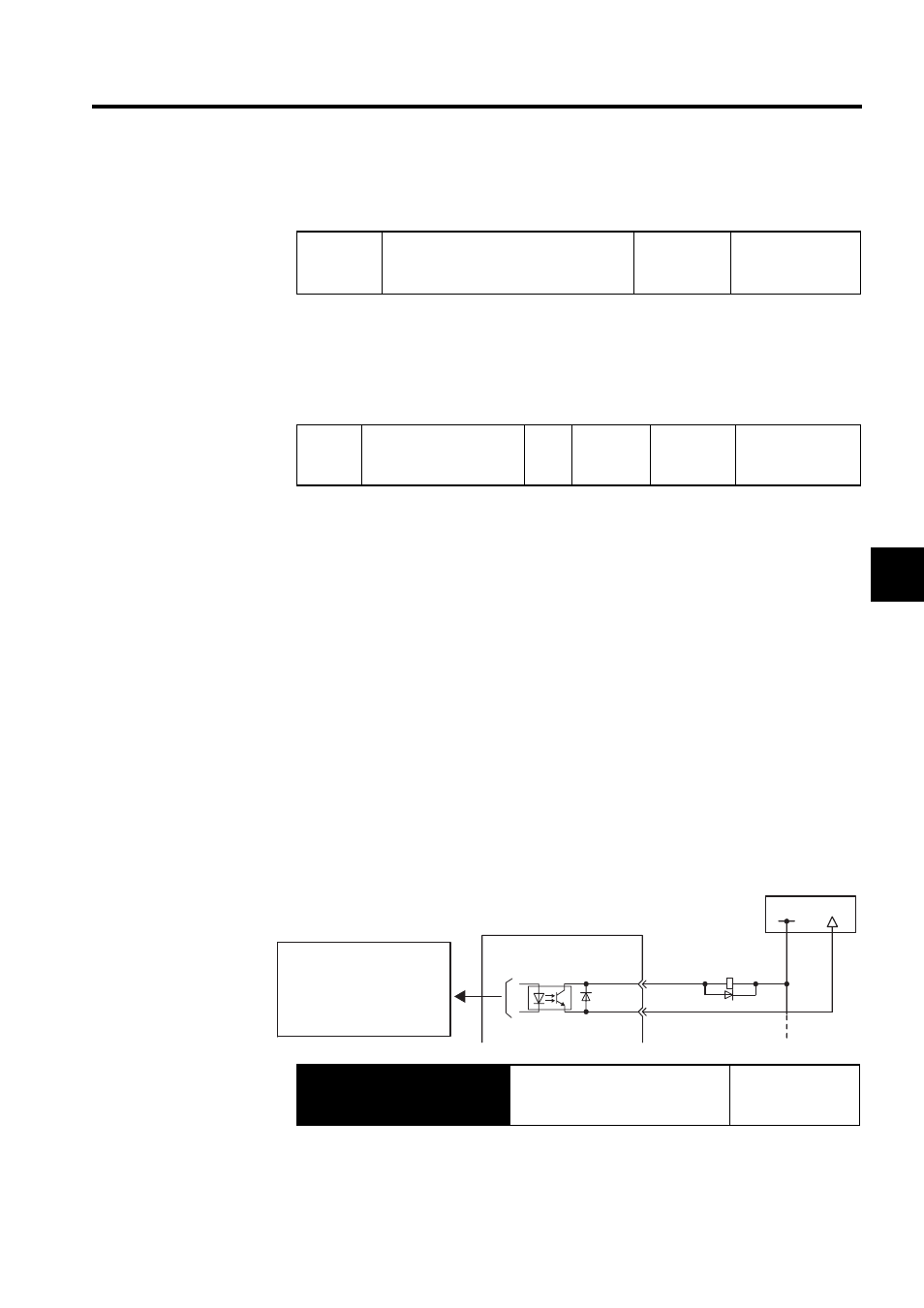
4.5.6 Using the Servo Ready Output Signal
The basic use and wiring procedures for the Servo Ready (/S-RDY) output signal (photocou-
pler output signal) are described below.
Servo Ready means there are no Servo alarms and the main circuit power supply is turned
ON. An added condition with absolute encoder specifications is that the SEN signal is at
high level and absolute data was output to the host controller.
Pn50E
Output Signal Selections 1
Factory
Setting:
3211
Speed/Torque
Control,
Position Control
Pn502
Rotation Detection Level Unit:
min
-1
Setting
Range:
1 to 10000
Factory
Setting:
20
Speed/Torque
Control,
Position Control
Output
→ /S-RDY CN1-29
Servo Ready Output Signal
Speed/Torque
Control,
Position Control
Photocoupler output
(per output)
Maximum operating voltage:
30 VDC
Maximum output current:
50 mA DC
SERVOPACK
I/O power supply
CN1-29
CN1-30
/S-RDY+
/S-RDY-
+24 V
0V