Battery replacement, Probe plate replacement – Ion Science Hydrosteel 6000 User Manual
Page 32
Hydrosteel 6000 MANUAL
Ion Science Ltd
Page 32 of 39
Unrivalled Detection. www.ionscience.com
Routine maintenance
If the reading is outside the limits stated above, the Hydrosteel analyser will need to be returned to ISL for
service and calibration. In this case it is a good idea to retest the hydrogen calibration after checking that all
connections have been made securely, there is sufficient gas pressure in the gas bottle and that the
instrument was zeroed in clean air free from any hydrogen background.
12) On completion of test disconnect all tubing and fittings and return to storage. IMPORTANT: ensure
the regulator is closed (see step 8).
Battery Replacement
When the battery symbol flashes, low battery power exists, and the batteries must be replaced. If the
instrument is left running until the batters fall below the operating voltage the instrument will restart then
sense the battery voltage is too low where will flash the start-up screen before displaying the message
battery voltage too low” and switching off.
If the instrument is switched on with extremely low (but not dead) batteries one of a number of things may
occur first the red LED will illuminate permanently the LCD will show a slight contrast as though the
instrument is trying to witch on. However in this state the instrument will not respond to key presses. Second
the instrument may display and hang at the start up screen. Again the instrument will not respond to key
presses. Third the instrument will start recognise that the battery voltage is too low and switch of in the same
way that it does when the batteries die.
1
Using the battery screwdriver provided, remove the battery cover at the underside of the analyser.
2
Remove the exhausted batteries from the battery tray and replace with four new AA alkaline batteries.
Note:
For the correct battery orientation, follow the symbols marked on the tray. Ensure that the
flying power lead is securely fastened to the battery tray.
3
Refit the tray into the analyser body.
To save power, always turn off the analyser when not in use.
Probe plate Replacement
Low temperature collector plate replacement
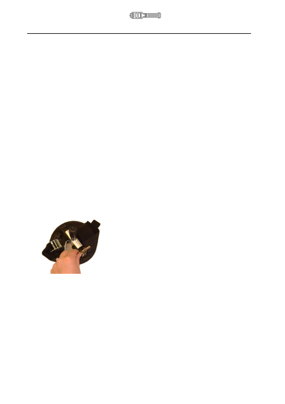
1
Unscrew the 1/8” nut on the collector plate sample tube to the bulkhead fitting on the back of the
probe assembly.
2
With the collector plate face facing towards you twist the collector plate clock wise 45
relative to the
probe assembly.
3
Slide the collector plate central spindle out of the central hole in the probe assembly.
4
Thread the gas sample tube from the collector through the leather hole in the probe assembly.
5
To secure the new collector plate, carry out the steps 4, 3, 2 and 1 in reverse.
High temperature collector plate replacement
1
Manually unscrew the collector handle from the assembly. Unscrew the HT sampling tube from the
HT probe. (The handle unscrews below the white heat shield
– please also see illustration under the
‘Using Hydrosteel 6000’ section of the manual.
2
Using the 2.5 mm hexagonal screwdriver from the HT-kit box, unscrew the hexagonal collector plate
locking screw, to release the collector plate from the bracket. Remove the plate.
3
Remove a new HT-R collector plate from the kit box. Handle the collector plates carefully. Being
designed for maximum flexibility, they are liable to permanently deform if dropped or mishandled.