Mode indicator, Reset to factory default, Using the lvl_adj line – Linx Technologies HUM-xxx-RC User Manual
Page 16
– –
– –
26
27
Mode Indicator
The Mode Indicator line (MODE_IND) provides feedback about the current
state of the module. This line switches at different rates depending on the
module’s current operation. When an LED is connected to this line it blinks,
providing a visual indication to the user. Figure 30 gives the definitions of
the MODE_IND timings.
Reset to Factory Default
The transceiver is reset to factory default by taking the Pair line high briefly
4 times, then taking and holding Pair high for more than 3 seconds. Each
brief interval must be high 0.1 to 2 seconds and low 0.1 to 2 seconds (1
second nominal high / low cycle). The sequence helps prevent accidental
resets. Once the sequence is recognized the MODE_IND line blinks the
Reset Acknowledgement defined in Figure 30 until the PAIR line goes
low. After the Reset Acknowledgement is shown and PAIR goes low, the
configuration is initialized. Factory reset also clears the Paired Module table
but does not change the local address. If the PAIR input timing doesn’t
match the reset sequence timing an Extended Pair Cancel sequence
is shown when PAIR goes low. The module reverts to normal operation
without a reset or pairing.
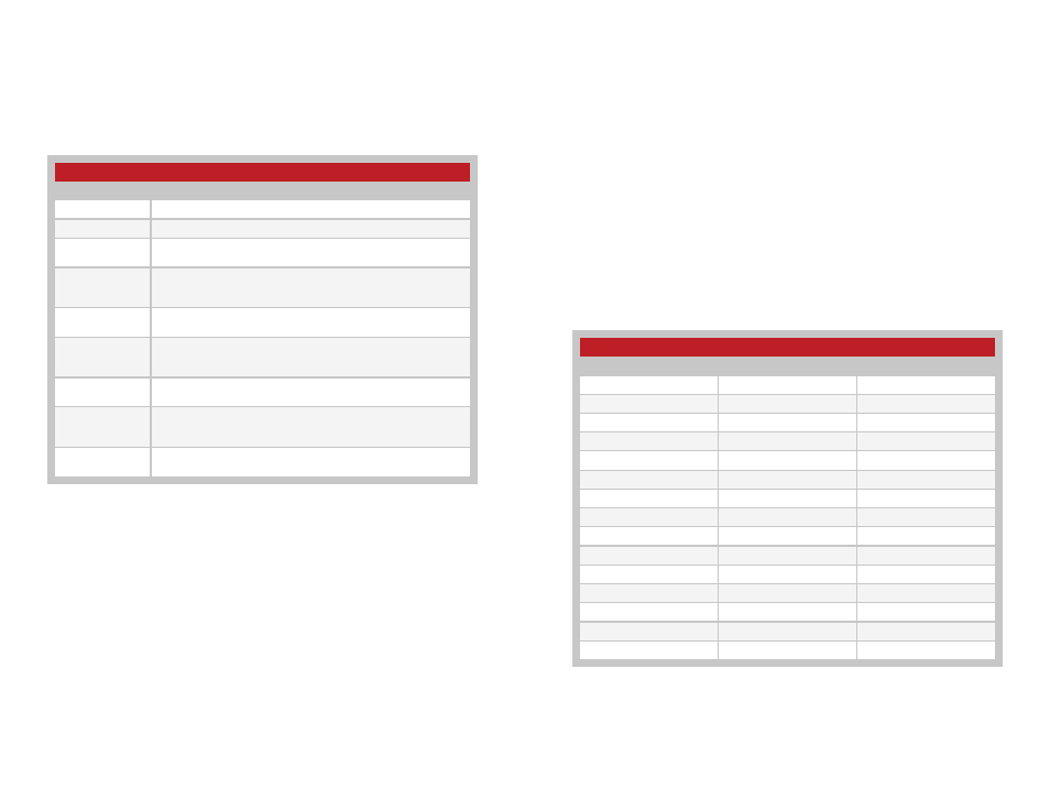
MODE_IND Timing
Module Status
Display
Transmit Mode
Solid ON when transmitting packets.
Receive Mode
Solid ON when receiving packets.
Pair Search
ON for 100ms, OFF for 900ms while searching for another unit
during the Pair process
Pair Found
ON for 400ms, OFF for 100ms when the transceiver has been
Paired with another transceiver. This is displayed for at least 3
seconds.
Pair Error
ON for 100ms, OFF for 100ms when the address table is full and
another unit cannot be added.
Remote Pair Error
ON for 100ms, OFF for 100ms, ON for 100ms OFF for 300ms
when the remote unit’s address table is full and a Pair cannot be
completed.
Pair Cancelled
ON for 100ms, OFF for 200ms, ON for 100ms when the Pair
process is cancelled.
Reset
Acknowledgement
ON for 600ms, OFF for 100ms, ON for 200ms, OFF for 100ms,
ON for 200ms and OFF for 100ms when the reset sequence is
recognized.
Extended Pair
Cancelled
Solid ON when the pairing operation is cancelled and waiting for the
PAIR line to go low.
Figure 30: MODE_IND Timing
Using the LVL_ADJ Line
The Level Adjust (LVL_ADJ) line allows the transceiver’s output power to be
easily adjusted for range control or lower power consumption. This is done
by placing a voltage on the LVL_ADJ line. This can be done using a voltage
divider or a voltage source. When the transceiver powers up, the voltage on
this line is measured and the output power level is set accordingly. When
LVL_ADJ is connected to V
CC
, the output power and current consumption
are the highest. When connected to ground, the output power and current
are the lowest. See the Typical Performance Graphs section (Figure 6) for a
graph of the output power vs. LVL_ADJ voltage.
Even in designs where attenuation is not anticipated, it is a good idea
to place resistor pads connected to LVL_ADJ so that it can be used if
needed. Figure 31 shows the voltages needed to set each power level and
gives the approximate output power for each level. The output power levels
are approximate and may vary part-to-part.
Power Level vs. LVL_ADJ Voltage Ratio
V
LVL_ADJ
/V
CC
ratio
P
OUT
@ 915MHz
P
OUT
@ 2.4GHz
0.00
–19.83
–27.96
0.08
–15.46
–26.50
0.15
–15.48
–24.88
0.23
–10.59
–21.32
0.30
–10.60
–18.74
0.38
–6.05
–16.94
0.45
–6.03
–14.66
0.53
–0.95
–10.82
0.61
–0.96
–9.26
0.68
4.30
–7.39
0.76
4.29
–5.26
0.83
6.66
–1.99
0.91
9.84
0.57
0.98
9.84
1.73
1.00
9.83
1.73
Figure 31: Power Level vs. LVL_ADJ Voltage Voltage Ratio