Basic hardware operation, The following steps describe how to use the humrc – Linx Technologies HUM-xxx-RC User Manual
Page 22
– –
– –
38
39
Basic Hardware Operation
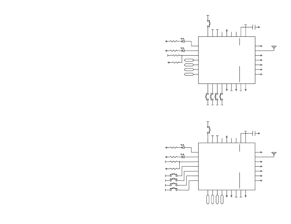
The following steps describe how to use the HumRC
TM
Series module with
hardware only. Basic application circuits that correspond to these steps are
shown in Figure 38.
1. Set the C0 and C1 lines opposite on both sides.
2. Press the PAIR button on both sides. The MODE_IND LED begins
flashing slowly to indicate that the module is searching for another
module.
3. Once the pairing is complete, the MODE_IND LED flashes quickly to
indicate that the pairing was successful.
4. The modules are now paired and ready for normal use.
5. Pressing a status line button on one module (the IU) activates the
corresponding status line output on the second module (the RU).
6. Taking the ACK_EN line high on the RU causes the module to send an
acknowledgement to the IU. The ACK_OUT line on the IU goes high to
indicate that the acknowledgement has been received. Tying the line
to V
cc
causes the module to send an acknowledgement as soon as a
command message is received.
This is suitable for basic remote control or command systems. No
programming is necessary for basic hardware operation. The Typical
Applications section shows additional example schematics for using the
modules.
The Command Data Interface section describes the more advanced
features that are available with the serial interface.
GND
VCC
GND
GND
GND
GND
GND
GND
GND
GND
GND
GND
VCC
S4
S5
S6
S7
VCC
VCC
VCC
VCC
VCC
GND
VCC VCC
GND
VCC
GND
VCC
GND
17
VCC
21
GND
18
RESET
22
LNA_EN
23
PA_EN
24
CMD_DATA_OUT
26
CMD_DATA_IN
27
ACK_EN
28
PAIR
29
S6
2
GND
25
S7
1
MODE_IND
30
ACK_OUT
31
LVL_ADJ
32
S5
3
S4
4
ANT
19
GND
20
S3
5
S2
6
S1
7
S0
8
C0
10
C1
11
POWER_DOW
N
12
LATCH_EN
13
GND
9
GND
16
GND
15
GND
14
GND
VCC
GND
GND
GND
GND
GND
GND
GND
GND
GND
GND VCC
S0
S1
S2
S3
VCC
VCC
VCC
VCC
GND
VCC
GND
VCC
GND
VCC
VCC
GND
17
VCC
21
GND
18
RESET
22
LNA_EN
23
PA_EN
24
CMD_DATA_OUT
26
CMD_DATA_IN
27
ACK_EN
28
PAIR
29
S6
2
GND
25
S7
1
MODE_IND
30
ACK_OUT
31
LVL_ADJ
32
S5
3
S4
4
ANT
19
GND
20
S3
5
S2
6
S1
7
S0
8
C0
10
C1
11
POWER_DOW
N
12
LATCH_EN
13
GND
9
GND
16
GND
15
GND
14
VCC
Figure 38: HumRC
TM
Series Transceiver Basic Application Circuits for Bi-directional Remote Control
A
B