Figure 2-1, magweb system diagram, 0 installation – Magnum Energy ME-MW-E User Manual
Page 7
Magnum Energy
Inverter/Charger
(with NETWORK port)
Remote Control
(ME- RC50 with revision 2.0,
ME-ARC50, ME-RTR)
,QYHUWLQJ
DC 12.6V 5A
SEL ECT
TECH
AG S
M ETER
SETUP
SHO RE
I NVERTER
CHARG ER
I N V
C H G
FA U LT
P W R
F
F
O
/
N
O
F
F
O
/
N
O
Optional
Internet
MagWeb
Device
Your
Network
Ethernet
Cable
See AGS and BMK Manuals
for connection instructions
SN: MW50000
PN: ME-MW-E
≥
© 2011 Magnum Energy, Inc.
3
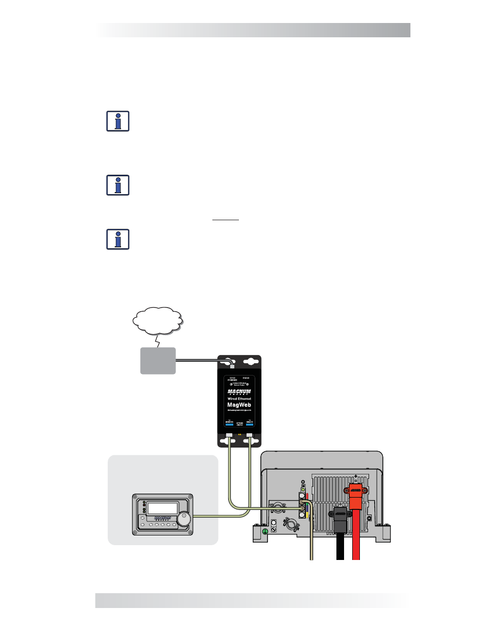
2.0 Installation
Figure 2-1, MagWeb System Diagram
(not to scale)
2.0 Installation
Before installing the MagWeb system, read this entire section so you can
thoroughly plan the details to ensure the overall system requirements are
accomplished. To assist in the planning and designing of your installation,
review the basic system diagram in Figure 2-1.
Info: Installations should be performed by qualifi ed person-
nel, such as a licensed or certifi ed electrician. It is the install-
er’s responsibility to determine which safety codes apply and
to ensure that all applicable installation requirements are
followed. Applicable installation codes vary depending on the
specifi c location and application.
Info: The MagWeb is plugged directly into a wired Ethernet
connection using the supplied Ethernet cable. The Ethernet
cable run is limited to 100 meters in total length. The Ethernet
cable must be connected to the Ethernet network and to the
MagWeb device before the MagWeb is connected to the inverter.
Info: Ensure that the MagWeb is connected to an “always on”
internet connection.
The MagWeb device is connected to the inverter using the supplied four-
conductor remote cable. If an ME-RC50, ME-ARC50, ME-RTR, or other
remote is installed in the system, it is connected to the MagWeb device.
Power is supplied to the MagWeb device from the Magnum inverter.