Fig.3, Operation – Sealey SSC11003 User Manual
Page 4
4.2. ROOM TEMPERATURE.
4.2.1. for correct functioning of the compressor the room
temperature must not be lower than 5°c or higher than 45°c.
4.2.2. If the compressor is operated at a room temperature
lower than the minimum value, the condensate could be
separated within the circuit resulting in water mixing with the
oil. the resulting deterioration in oil quality would fail to
guarantee the even formation of an effective lubricating film
between moving parts with the possibility of seizure.
4.2.3. If the compressor works at a room temperature higher than
maximum value, the compressor would take in air that is too
hot, which would prevent the heat exchanger from adequately
cooling the oil in the circuit, raising the working temperature of
the machine, thus causing the thermal safety device to trip,
which stops the compressor due to the excessive temperature
of the air/oil mixture at the screw outlet.
4.2.4.
The maximum temperature of the room is to be measured
while the compressor is running.
4.3. OPERATING ENVIRONMENT.
the compressor must be installed in a large room that is well-
ventilated, dust-free and sheltered away from rain and frost.
the compressor takes in a large amount of air that is required
for internal ventilation. A dusty atmosphere would in time
cause damage and inefficient performance. Dust drawn into
the machine will be taken into the air filter causing it to clog
rapidly. Incoming dust will also settle onto the components and
will be blown against the cooling radiator, consequently
compromising the efficiency of the heat exchanger. It is
therefore obvious that the cleanliness of the area in which the
compressor is installed is crucial for the optimum efficiency of
the machine, avoiding excessive running and maintenance
costs. to facilitate maintenance and to create a favourable
circulation of air, the compressor must have sufficient free
space all around it as shown in fig.2.
4.4. UNSUITABLE ENVIRONMENTAL CONDITIONS.
4.4.1.
DO NOT install the compressor in an environment where there
is a risk of fire and/or explosion.
4.4.2.
DO NOT install the compressor in an environment where there
is a risk that the machine may overheat. (maximum permitted
operating temperature 45ºc).
4.4.3.
DO NOT install the compressor in an atmosphere where the
humidity will be higher than 80%.
4.4.4.
NOTE: this compressor is designed to work with a tank of a
specific size i.e.100ltr. no liability will be accepted for any
related malfunctions or problems resulting from the
compressor being connected to a different tank. the
compressor should not be modified in any way.
Original Language Version
4.5. CONNECTING TO THE TANK COMPRESSED AIR OUTLET.
connect the compressor to the air delivery system using the
quick coupler (fig3.A). use hose of the same diameter (or
greater) as the compressor outlet. If a connection hose leaks
or is faulty never try to repair it but replace with a sound one.
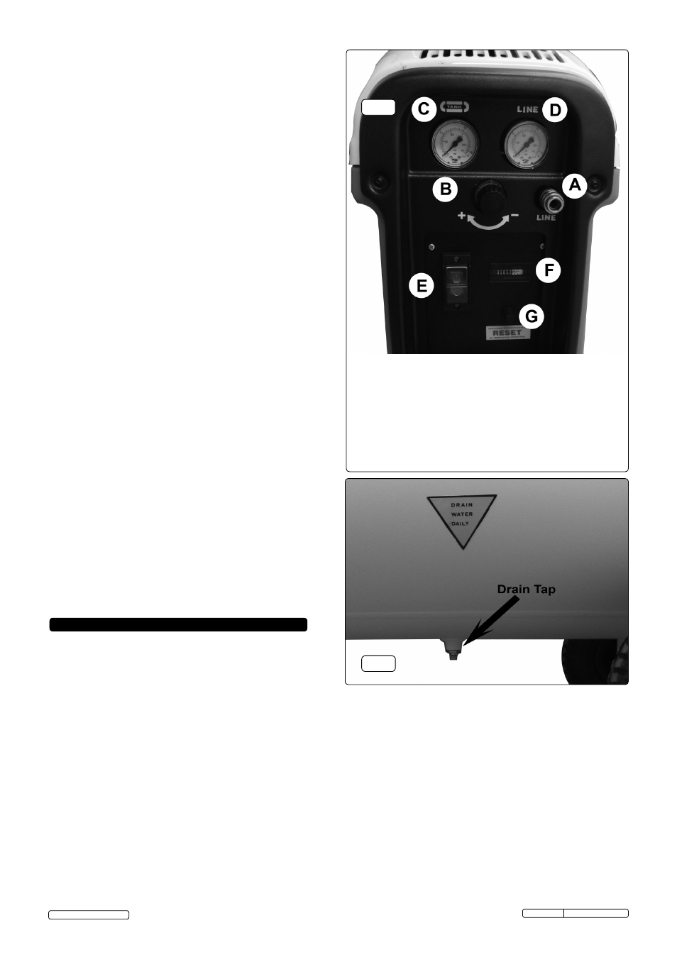
fig.3
fig.3
5. OPERATION
WARNING! Ensure that you have read, understood and
apply Section 1 safety instructions.
NOTE:
take care when selecting tools for use with the
compressor. Air tool manufacturers normally express the
volume of air required to operate a tool in cubic feet per minute
(cfm). this refers to free air delivered by the compressor (‘air
out’) which varies according to the pressure setting. Do not
confuse this with the compressor displacement which is the air
taken in by the compressor (‘air in’). ‘Air out’ is always less
than ‘air in’ due to losses within the compressor.
5.1. INITIAL START.
5.1.1.
Upon first use or following an extended inactive period switch
on and off (fig3.E.) for 3 or 4 seconds several times. This is to
start the oil circulating.
5.1.2. Switch the machine back on with the drain tap (fig.4) open
and run for 2 minutes to circulate the oil thoroughly without
building pressure.
5.1.3. close the drain tap and re-start the compressor; allow to build
up to full pressure at which point the pump will unload and run
idle for 2 minutes.
5.1.4. If there has been no air use during this 2 minutes, the machine
will shut down to stand-by mode.
5.1.5. When the pressure drops by 2 bar, the machine will switch on
again to regain full pressure.
5.1.6: It is not necessary to repeat this procedure in normal use.
A: Air line quick connector
B: Pressure regulator
C: Tank pressure gauge
D: Line pressure gauge
E: On/Off switch
F: Hours counter
G: Reset button
fig.4
5.2. PRESSURE REGULATION.
5.2.1. The tank pressure is shown by gauge fig.3.c.
5.2.2. The line (delivery) pressure is shown by gauge fig
.3.D. and is
adjusted by means of the pressure regulator fig.3.B.
to increase pressure: turn clockwise; to decrease: turn
anticlockwise.
5.2.3.
NOTE: the regulator should be turned back to zero before
running the machine for the first time, and the pressure
increased to the desired level when the tank is full. failure to
do this could result in damage to the diaphragm within the
regulator.
5.3. SWITCHING OFF
5.3.1. Switch off using on/off switch (fig.3.E)
DO NOT switch off by
switching the mains supply off.
5.3.2. When switched off by the on/off switch, the compressor will
continue to run for some time in order to clear the pump of oil.
5.4. DUTY CYCLE
the recommended duty cycle is 80%, meaning that the
machine should not be run continuously for more than
48 minutes in one hour.
ssc11003 Issue: 1 - 03/05/13
© Jack sealey Limited