Fi g.2 fi g.1, Introduction & specification, Preparation for mig welding – Sealey INVMIG160 User Manual
Page 2
2.1.
Manufactured with a pressed steel outer casing giving this unit a weight of only 21kg. Inverter welders offer many advantages over
traditional transformer type welders. This 2-in-1 welder uses state-of-the-art technology to achieve MIG and arc welding. Automatic
Arc-Force circuitry makes this unit suitable for arc welding a variety of rods including rutile, basic and stainless steel from Ø1.6mm to
Ø4.0mm. Fan cooled DC power supply for MIG welding, suitable to weld steel, stainless steel, copper, nickel, titanium and their alloys.
Includes rocker switch to allow operator to switch between MIG and arc welding modes. Features high frequency start to enable fast
and responsive striking of the arc. Thermal overload protection which automatically switches unit off when it exceeds maximum
temperature. Fully functional front panel with self explanatory pictures for each dial and switch, making this easier and accessible to
use. Current and voltage switches to allow control of current and voltage. Wire feed control used to control the speed of wire fed
through the torch during welding. Burn back time control allows the operator to manually choose desired length of electrode wire which
protrudes from torch after welding. Polarity change terminals allow the operator to change polarity of welding torch depending on
whether the applications are MIG welding or flux-cored welding. Includes 3mtr MIG torch, 2.5mtr earth cable, gas hose and regulator
and 0.6/0.8 contact tip
2.2. IMPORTANT: These instructions contain information you require to prepare your machine for welding, together with a maintenance
section. If you have no previous experience the instructions are not intended to show you how to become a welder. Should you have no
experience, we recommend that you seek training from an expert source. MIG welding is relatively easy to perform, but does
require a steady hand and time practising under supervision with scrap metal as it is only with continued practice that you will achieve
the desired results.
1.3. GAS
SAFETY
Store gas cylinders in a vertical position only and ensure that the storage area is correctly secured.
DO NOT
store gas cylinders in areas where temperature exceeds 50°C. DO NOT use direct heat on a cylinder. Always keep gas
cylinders
cool.
DO NOT
attempt to repair or modify any part of a gas cylinder or valve and DO NOT puncture or damage a cylinder.
DO NOT
obscure or remove any official cylinder labels. Always check the gas identity before use. Avoid getting gas cylinders oily or
greasy.
DO NOT
lift a cylinder by the cap, guard or valve. Always keep caps and guards in place and close valve when not in use.
2. INTRODUCTION & SPECIFICATION
Model No:
. . . . . . . . . . . . . . . . . . . . . . . . . . . . . . . . . . . . . . . . . . . . . . . . . . . . . . . . .INVMIG160
Duty Cycle, MIG: . . . . . . . . . . . . . . . . . . . . . . . . . . . . . . . . . . . . . . . 35% @ 160A, 60% @ 120A
Arc (MMA): . . . . . . . . . . . . . . . . . . . . . . . . . . . . . . . . . . 35% @ 160A, 60% @ 120A
Electrode Capacity: . . . . . . . . . . . . . . . . . . . . . . . . . . . . . . . . . . . . . . . . . . . . . . . . ø1.6 - 4.0mm
Maximum Wire Spool: . . . . . . . . . . . . . . . . . . . . . . . . . . . . . . . . . . . . . . . . . . . . . . . . . . . . . . 5kg
Absorbed Power: . . . . . . . . . . . . . . . . . . . . . . . . . . . . . . . . . . . . . . . . . . . . . . . . . . . . . . . . 7.8kW
Supply: . . . . . . . . . . . . . . . . . . . . . . . . . . . . . . . . . . . . . . . . . . . . . . . . . . . . . . . . . . . . . . .230V ac
Insulation: . . . . . . . . . . . . . . . . . . . . . . . . . . . . . . . . . . . . . . . . . . . . . . . . . . . . . . . . . . . . . . . . . . F
Protection: . . . . . . . . . . . . . . . . . . . . . . . . . . . . . . . . . . . . . . . . . . . . . . . . . . . . . . . . . . . . . IP21S
Weight: . . . . . . . . . . . . . . . . . . . . . . . . . . . . . . . . . . . . . . . . . . . . . . . . . . . . . . . . . . . . . . . 20.72kg
3. PREPARATION FOR MIG WELDING
NOTE:
The main (On/Off) switch is located on the rear plate
of the machine.The power indicator light (fig.1.3) is lit when
the welder is live.
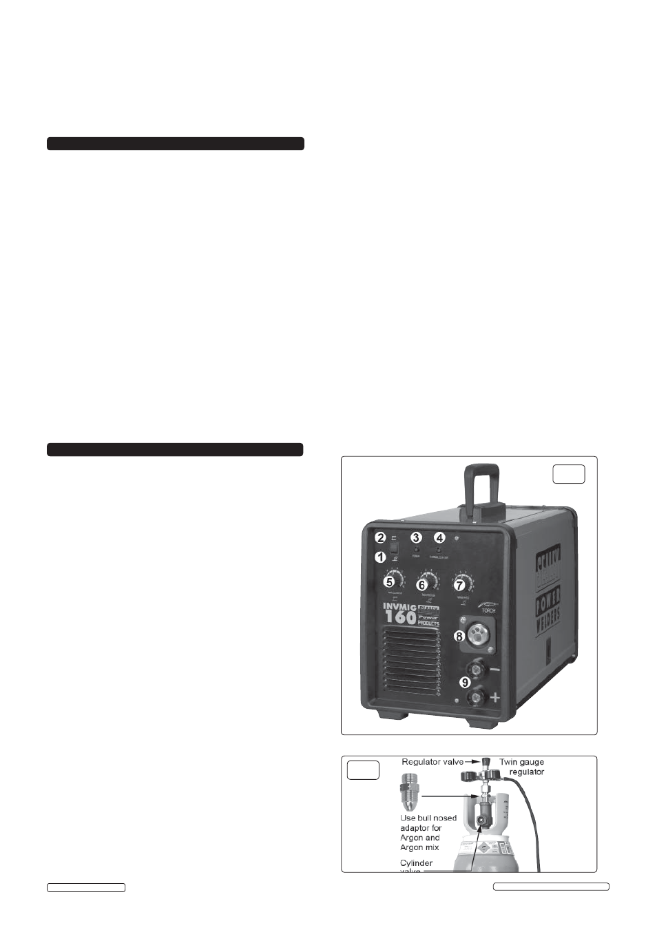
3.1.
Switch selector switch to position 'MIG' position (fig.1.1).
3.2.
COUPLING TO GAS CYLINDER.
ATTACHING THE REGULATOR.
(fig.2) Whichever gas you
are using it is advisable to 'crack' the cylinder valve before
attaching the regulator. This means opening and closing the
valve very quickly in order to blow away any dust and dirt
that may have accumulated in the gas outlet. Stand to one
side whilst doing this.
3.2.1 .
CO² GAS. Ensure that the threads on the gas bottle are
undamaged
and free of oil and grease before attaching the
regulator. (Oil or grease in the presence of high pressure
gases can be explosive.) Ensure that the regulator has an
undamaged gasket fitted. The regulator will screw directly to
the threads on the gas bottle. Tighten with a wrench.
3.2.2.
ARGON GAS OR ARGON MIXTURES.
Cylinders containing
argon gas and argon mixtures have a female thread and will
require the use of a Bull Nose Adaptor to attach the regulator to
the cylinder as indicated in fig.2. Ensure that the threads on the
gas bottle are undamaged and free of oil and grease before
attaching the regulator. (Oil or grease in the presence of high
pressure gases can be explosive.) Fit the Bull Nose Adaptor
to the cylinder first and tighten with a wrench.
3.2.3.
Slide a hose clip over each end of the gas hose supplied.
Push one end of the hose onto the regulator outlet and the
other end over the gas inlet spigot on the back of the welder.
Tighten the clips to ensure a good seal.
3.2.4.
Close the regulator valve by turning it anticlockwise before
opening
the cylinder valve. Stand to one side when opening
the cylinder valve.
3.2.5.
Set the regulator flow rate to 5-8 litres/min depending on the
material to be welded, and whether there are draughts
which are strong enough to disturb the gas flow.
fi g.2
fi g.1
Original Language Version
INVMIG160 | Issue: 2S - 08/01/15
© Jack Sealey Limited