Fig.12, Fig.13, Mma (arc) welding 6. preparation – Sealey INVMIG160 User Manual
Page 5: Welding procedure
4.1.5. To weld aluminium use:
● Argon gas,
● 0.8mm Contact Tip (MIG927),
● 0.8mm Aluminium Wire, (MIG/2KAL08).
A clean torch liner is essential, as any contamination of the aluminium wire will produce a poor weld.
4.1.6. Overload Protection. Thermostatic overload protection is provided. When an overload has occurred, leave
the unit to cool. The thermostat will automatically reset the unit when the temperature has returned within limits.
4.1.7. Burn Back Timer. The INVMIG160 is fitted with a variable Burn Back Timer, the control knob of which is
situated inside the case, above the wire feed assembly. The function of this timer is to leave a controlled
amount of welding wire protruding after the weld current switches off. This prevents the wire melting onto
the
electrode.
4.1.8. The interval can be adjusted by moving the knob shown in fig.12.
fig.12
For arc welding the selector switch needs to be in the 'Arc' setting. (fig.1.2)
WARNING! Before using as an arc welder, ensure that the torch connecter plug is disconnected from both + and - output
sockets.
(fig.11)
WARNING!
Ensure that the inverter is not plugged into the mains power supply before connecting or disconnecting cables.
For electrical installation, see Safety Instructions (Section 1).
WARNING!
Failure to follow the electrical safety instructions may affect the operating performance and could damage the
built-in safety system which, in turn, could result in personal injury or fatality and will invalidate the warranty.
5.1.
WELDING
CABLE
ELECTRODE
HOLDER
CONNECTION
NOTE:
Arc welding cables are not supplied with machine. Sealey part no: INVMMA2 is suItable.
Before connecting cables it is important to refer to the electrode manufacturer’s instructions on the electrode packaging which will
indicate the correct polarity connection for the electrode, together with the most suitable current to use.
5.2.
ARC WELDING
In principle, when ARC welding the Electrode Holder is normally connected to the “POSITIVE” (+) terminal (fig.1.9).
5.3.
WELDING RETURN CABLE- (WORK CLAMP) CONNECTION
The WORK CLAMP cable is connected to the terminal not occupied by the electrode holder cable.
The clamp is connected to:
a) The workpiece, or
b) A metallic work bench. The connection must be as close to the proposed weld as possible.
WARNING!
Cable connectors must be turned fully into the quick plugs to ensure a good electrical contact. Loose
connections will cause overheating, rapid deterioration and loss in efficiency. DO NOT use welding cables over 10m in length.
With the exception of a metallic workbench DO NOT connect the return cable to any metallic structure which is not part of
the workpiece, as this will jeopardise weld quality and may be dangerous.
5. MMA (ARC) WELDING
6.
PREPARATION
6.1.
The welding current must be regulated according to the diameter of the
electrode in use and the type of joint to be welded. See diameter/current chart
to the right. Welding current is controlled by the amperage regulator (fig.1.5).
6.2.
Further consideration must be given to the location of the weld, for example:
Welds that are performed on a horizontal surface require a higher voltage than
those performed on a vertical or overhead surface.
6.3.
The mechanical character of the weld will be determined not only by the current
used, but also by the diameter and quality of the electrode, the length of the arc
and the speed and position of the user. The condition of the electrode is an
important factor and it must never be wet or damp.
6.4.
Ensure that the workpiece is correctly secured before operating the inverter.
Electrode
Welding Current
(Amps)
Diameter (mm) .....Min .................. Max
1.6
...........................25
.................... 50
2.
.............................40
.................... 80
2.5
...........................60
.................... 110
3.2
...........................80
.................... 160
4
..............................120
.................. 200
For Guidance Only
WARNING!
Ensure
that you read, understand and follow the safety instructions. Place the welding mask in front of your
face
before
striking the arc.
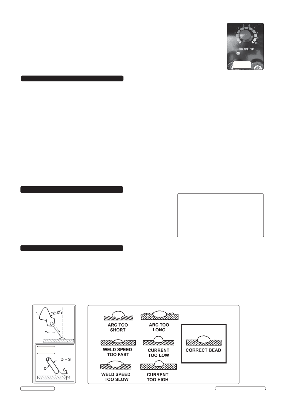
7.1. ARC
WELDING
7.1.1. Strike the electrode tip on the workpiece as if you were striking a match.
WARNING! DO NOT hit the electrode on the workpiece, as this may damage the electrode.
7.1.2. As soon as the arc is struck, maintain a distance from the workpiece equal to the diameter of the electrode. Keep this distance as
constant
as possible for the duration of the weld. As you advance along the workpiece the angle of the electrode must be maintained
at between 20º and 30º. See fig.13.
7.1.3. At the finish of the weld, bring the end of the electrode backward in order to fill the weld crater and then quickly lift the electrode from
the weld pool to extinguish the arc.
WARNING!
Hot metal such as electrode stubs and workpieces should never be handled without gloves.
7. WELDING PROCEDURE
fig.13
Original Language Version
© Jack Sealey Limited
INVMIG160 | Issue: 2S - 08/01/15