Fig.10, Fig.11, Mig/mag welding – Sealey INVMIG160 User Manual
Page 4
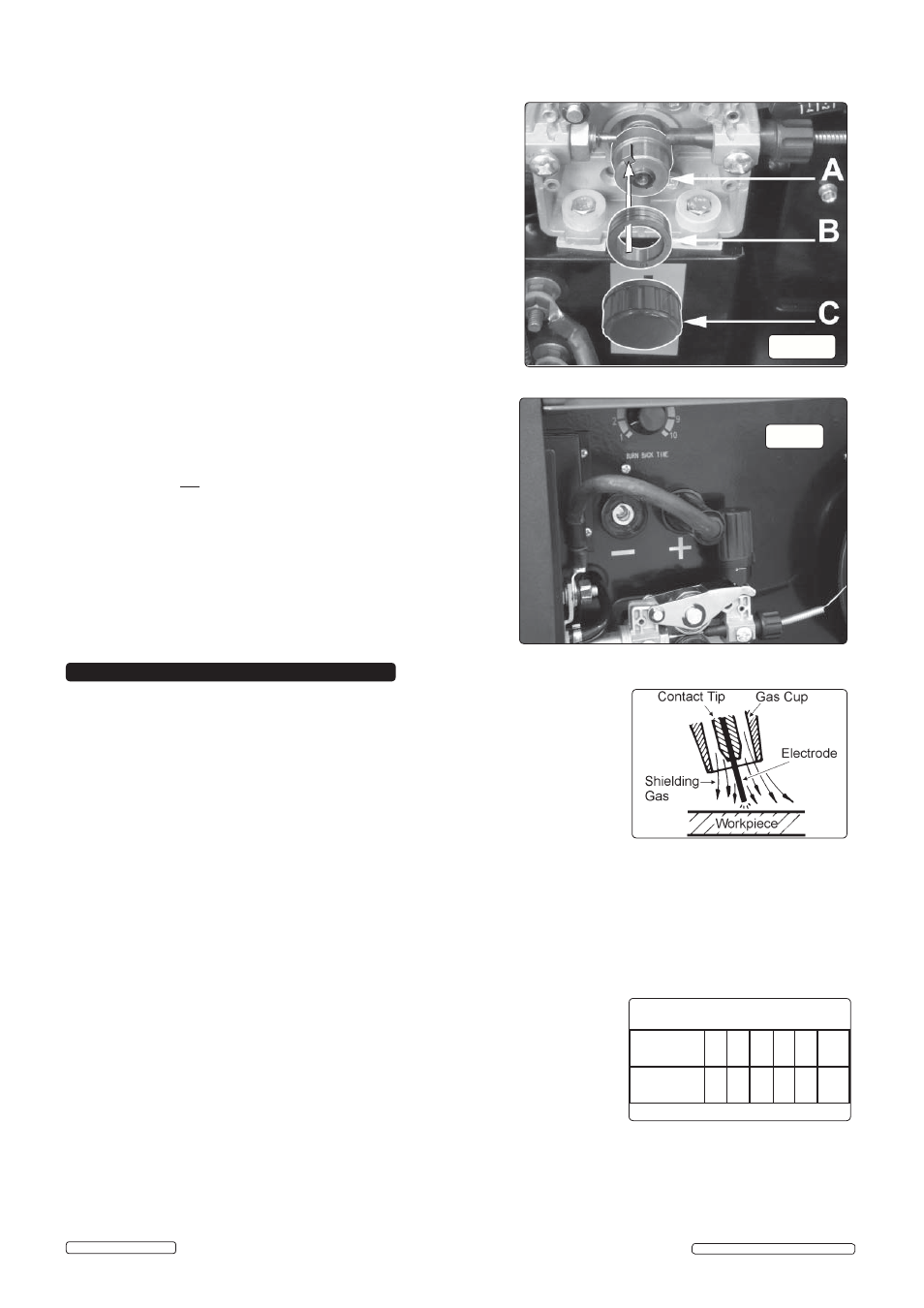
fig.10
3.8.
CONVERTING TO GASLESS WELDING.
When delivered, your welder
is set up for gas welding with the torch cable connected to the positive
(+) terminal and the earthing cable connected to the negative (-)
terminal.
(fig.11)
3.8.1. To weld without gas (using flux cored wire) you must reverse the
polarity and connect the torch cable to the negative (-) terminal and
the earthing cable to the positive (+) terminal (fig.11).
Ensure that the machine is switched off and unplugged from
the mains supply before carring our this task.
3.8.2. Safely disconnect the gas.
3.8.3. Fit a 1mm tip to the torch.
3.8.4. Mount the flux cored wire reel and feed it through to the torch.
3.7.6. Check that the key in the carrier (A) is properly seated in its slot.
3.7.6. Check that the key in the carrier (A) is properly seated in its slot.
Ensure that the slot on the inside face of the drive roller (B) is aligned
Ensure that the slot on the inside face of the drive roller (B) is aligned
with the key and slide the roller back onto the carrier.
with the key and slide the roller back onto the carrier.
3.7.7. Screw the black roller retaining knob (C) back on to the end of the
3.7.7. Screw the black roller retaining knob (C) back on to the end of the
drive shaft and tighten.
drive shaft and tighten.
fig.11
A spool of welding wire is positioned on the welder’s spool holder and automatically fed through an
insulated liner in the torch to the tip. The torch assembly consists of a switch, liner, gas hose, and
control cable. The switch activates the wire feed roller and the gas flow. Conversely, releasing the
switch stops the wire feed and gas flow. The weld current is transferred to the electrode (the wire)
from the contact tip at the end of the torch. A gas cup fits over the contact tip to direct the gas flow
towards the weld ensuring that the arc welding process is shielded from oxidising air contaminates.
`
The shielding gas also assists heating of the weld materials. (The welder can also be used in
gasless mode using flux cored wire). The torch is connected to the positive side of a DC rectifier,
and the negative clamp is attached to the workpiece.
IMPORTANT: Should you have no welding experience, we recommend you seek training from
an expert source to ensure your personal health & safety. Good MIG welding may be achieved
only with continued, supervised practice.
4.1.
PREPARATION FOR WELDING
IMPORTANT: BEFORE YOU COMMENCE, MAKE SURE THE MACHINE IS SWITCHED OFF AT THE MAINS. IF WELDING A CAR,
DISCONNECT THE BATTERY OR FIT AN ELECTRONIC CIRCUIT PROTECTOR. WE STRONGLY RECOMMEND THE USE OF
SEALEY "PROSAF/12V OR 24V" IN ORDER TO PROTECT SOPHISTICATED ELECTRONICS. ENSURE YOU HAVE READ &
UNDERSTOOD THE ELECTRICAL SAFETY INSTRUCTIONS IN CHAPTER 1.
4.1.1. Connecting the Earth Lead.
To ensure a complete circuit, the earth lead must be securely attached to the workpiece that is to be welded.
a) Best connection is obtained by grinding clean the point of contact on the workpiece before connecting the earth clamp.
b) The weld area must also be free of paint, rust, grease, etc.
c) When welding a vehicle, be sure the vehicle battery is disconnected or fit an Electronic
Circuit Protector available from your Sealey dealer.
4.1.2. Voltage Switch (fig1.6) Set the switch to position 1 or 2 for welding up to 2mm thickness.
Use settings 3, 4, 5, 6. for thicker welds.
4.1.3. Setting the welder controls. In principle, the lower the power required,
the
slower
the
wire speed. See setting chart for voltage and corresponding wire speeds. Note: these
settings are only a guide and will vary according to the operators experience.
4.1.4. Welding mild steel
To weld mild steel you can use CO² gas for most tasks where spatter and the high build up of weld do not pose a problem. Welding
with a long arc reduces penetration and widens the arc. This in turn results in more spatter. A long welding arc can be appropriate
for welding butt joints in thin materials. Welding with a short arc, at the same weld settings, results in greater penetration and a
narrower weld and reduces the amount of spatter. To achieve a consistent spatter free and flat weld, you must use an argon/CO²
mixture.
4. MIG/MAG
WELDING
Wire: 0.6mm Steel
Argon/CO2 Mix
Voltage
Step:
1
2
3
4
5
6
Wire
Speed:
5
6
7
8
9
10
Settings shown as Guide Only
3.6.1 Tension between rollers is checked by slowing down the wire between gloved fingers. If top feed roller skids the tension is correct. Use
3.6.1 Tension between rollers is checked by slowing down the wire between gloved fingers. If top feed roller skids the tension is correct. Use
as low a tension as possible; too high a tension could crush the wire and result in a blown fuse.
as low a tension as possible; too high a tension could crush the wire and result in a blown fuse.
Original Language Version
© Jack Sealey Limited
3.7.
3.7.
TURNING/CHANGING THE DRIVE ROLLER
TURNING/CHANGING THE DRIVE ROLLER
.. (See fig.10)
(See fig.10)
Ensure that the wire diameter (0.6mm/0.8mm) used is matched by the
correct groove size in the drive wheel and the correct tip size on the
torch as well as the correct torch liner. Failure to do so could cause the
wire to slip and/or bind.
3.7.1. Referring to fig.10, open the wire feed mechanism by pushing the
locking/wire tension knob (1) down to the right allowing the pressure
roller carrier (2) to spring up revealing the feed roller.
3.7.2 Remove knob (C) and put to one side.
3.7.2 Remove knob (C) and put to one side.
3.7.3. The roller carrier (A) is keyed to the main drive shaft and the drive
3.7.3. The roller carrier (A) is keyed to the main drive shaft and the drive
roller (B) is keyed to the carrier, see below. Place a finger onto the end
roller (B) is keyed to the carrier, see below. Place a finger onto the end
of the drive shaft to prevent the carrier moving and slide the drive roller
of the drive shaft to prevent the carrier moving and slide the drive roller
off the carrier with your other hand.
off the carrier with your other hand.
3.7.4. The size of each wire feed groove is printed on the edge of the roller
on the same side as the groove.
3.7.5. Turn the roller over to use the other groove or use a roller with different
3.7.5. Turn the roller over to use the other groove or use a roller with different
sized grooves as required. The groove to be used should be positioned
sized grooves as required. The groove to be used should be positioned
furthest away from you to be in line with the drive path.
furthest away from you to be in line with the drive path.
INVMIG160 | Issue: 2S - 08/01/15